전기 시스템
전기 시스템의 모델링, 제어 및 시뮬레이션을 보여주는 예제를 살펴보십시오.
카테고리
- Simulink와 Simscape의 전기 회로
Simulink®와 Simscape™의 전기 회로 예제
- 배터리
배터리 예제
추천 예제
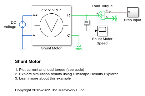
션트 모터
이 예제에서는 션트 모터의 모델을 보여줍니다. 션트 모터에서 계자 권선과 전기자 권선은 병렬로 연결됩니다. 등가 회로 파라미터는 전기자 저항 Ra = 110옴, 계자 저항 Rf = 2.46킬로옴, 역기전력 계수 Laf = 5.11입니다. 역기전력은 Laf*If*Ia*w로 주어지며, 여기서 If는 계자 전류, Ia는 전기자 전류, w는 회전자 속도(단위: 라디안/초)입니다. 회전자 관성 J는 2.2e-4kgm^2이고 회전자 감쇠 B는 2.8e-6Nm/(rad/s)입니다.
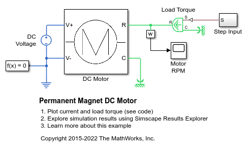
영구 자석 DC 모터
이 예제에서는 테스트 하네스와 Simscape™ 블록을 사용하여 DC 모터의 무부하 속도, 무부하 전류, 스톨 토크에 대한 제조업체 사양을 검증하는 방법을 보여줍니다.

비선형 양극성 트랜지스터
이 모델은 Ebers-Moll 등가 회로를 기반으로 하는 비선형 양극성 트랜지스터의 구현을 보여줍니다. R1과 R2는 공칭 동작점을 설정하고, 소신호 이득은 대략 R3/R4 비에 따라 설정됩니다. 1uF 디커플링 커패시터는 1KHz에서 무시 가능한 임피던스를 나타내도록 선택되었습니다. 주파수 응답이 생성될 수 있도록 선형 모델이 구성되어 있습니다.
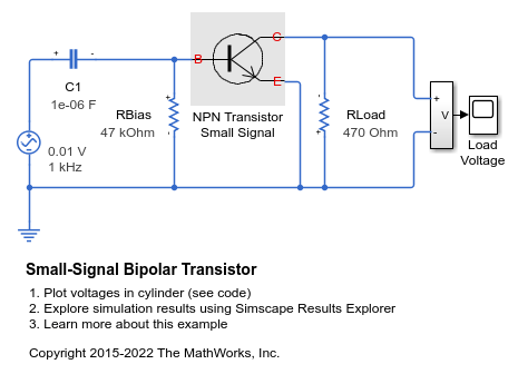
소신호 양극성 트랜지스터
이 모델은 공통 이미터 증폭기의 성능을 평가하기 위해 소신호 등가 트랜지스터 모델을 사용하는 방법을 보여줍니다. 47K 저항기는 공칭 동작점을 설정하는 데 필요한 바이어스 저항기이고, 470옴 저항기는 부하 저항기입니다. 트랜지스터는 회로 파라미터 h_ie(베이스 회로 저항), h_oe(출력 어드미턴스), h_fe(순방향 전류 이득), h_re(역전압 전달 비율)를 갖는 하이브리드 파라미터 등가 회로로 표현됩니다. 설정된 파라미터는 일반적으로 BC107 Group B 트랜지스터를 기준으로 합니다. 이득은 대략 -h_fe*470/h_ie =-47로 주어집니다. 입력 저항 h_ie에 비해 1KHz에서 무시 가능한 임피던스를 나타내도록 1uF 디커플링 커패시터가 선택되었으므로 피크 출력 전압은 47*10mV = 0.47V여야 합니다.
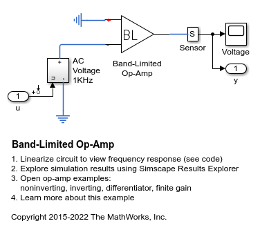
Band-Limited Op-Amp
How higher fidelity or more detailed component models can be built from the Foundation library blocks. The model implements a band-limited op-amp. It includes a first-order dynamic from inputs to outputs, and gives much faster simulation than if using a device-level equivalent circuit, which would normally include multiple transistors. This model also includes the effects of input and output impedance (Rin and Rout in the circuit), but does not include nonlinear effects such as slew-rate limiting.
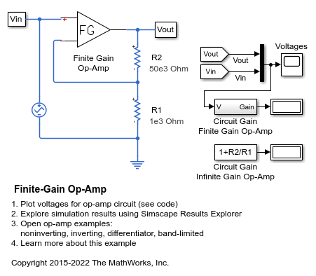
Finite-Gain Op-Amp
How higher fidelity or more detailed component models can be built from the Foundation library blocks. The Op-Amp block in the Foundation library models the ideal case whereby the gain is infinite, input impedance infinite, and output impedance zero. The Finite Gain Op-Amp block in this example has an open-loop gain of 1e5, input resistance of 100K ohms and output resistance of 10 ohms. As a result, the gain for this amplifier circuit is slightly lower than the gain that can be analytically calculated if the op-amp gain is assumed to be infinite.
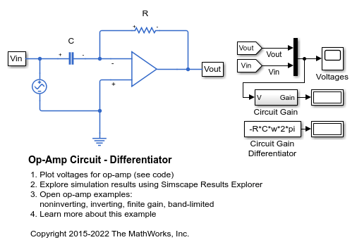
Op-Amp 회로 - 미분기
이 모델은 PID 제어기의 일부로 사용되기도 하는 미분기를 보여줍니다. 또한 일부 이상화된 회로에서 숫자형 시뮬레이션 문제가 어떻게 발생할 수 있는지를 보여줍니다. 모델은 커패시터 직렬 기생 저항을 디폴트 값인 1e-6옴으로 설정한 상태에서 실행됩니다. 이를 0으로 설정하면 경고가 발생하고 시뮬레이션이 매우 느려집니다. 자세한 내용은 사용자 안내서를 참조하십시오.

OP-Amp 회로 - 반전 증폭기
이 예제에서는 표준 반전 op-amp 회로의 모델을 보여줍니다. 이득은 -R2/R1로 지정됩니다. R1 = 1K 옴 및 R2 = 10K 옴이면 0.1V 피크 간 입력 전압이 1V 피크 간 전압으로 증폭됩니다. Op-Amp 블록은 이상적인(무한 이득) 소자를 구현하므로 출력 부하에 관계없이 이 이득을 달성할 수 있습니다.
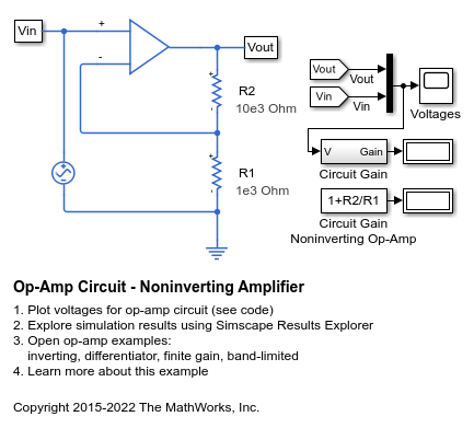
OP-Amp 회로 - 비반전 증폭기
이 모델은 비반전 op-amp 회로를 보여줍니다. 이득은 1+R2/R1으로 지정되며, 값을 R1=1K옴 및 R2=10K옴으로 설정하면 0.1V의 피크 간 입력 전압이 1.1V의 피크 간 전압으로 증폭됩니다. Op-Amp 블록이 이상적인(무한 이득) 소자를 구현하므로 이 이득은 출력 부하에 관계없이 달성됩니다.

비선형 인덕터
이 예제에서는 전류에 따라 인덕턴스가 달라지는 비선형 인덕터의 구현을 보여줍니다. tanh 함수는 비선형 플럭스-전류 관계를 정의합니다. 플럭스는 큰 전류에서 포화되는데, 이 현상은 예를 들어 철심 인덕터에서 발생할 수 있습니다.

전파 브리지 정류기
이 예제에서는 120VAC를 12VDC로 변환하는 변압기에서 특정 부하에 맞게 커패시터의 크기를 조정하는 방법을 보여줍니다. 시스템은 이상적인 AC 변압기와 전파 브리지 정류기로 모델링되었습니다.

회로 차단기
이 예제는 회로 차단기를 모델링하는 방법을 보여줍니다. 전기기계 차단기 메커니즘이 1차 시정수를 사용하여 근사되며, 기계적 힘이 부하 전류에 비례한다고 가정합니다. 이 간단한 표현은 완전한 시스템의 대형 모델에 사용하기에 적합합니다. 20V 공급이 1초에 적용되면 회로 차단기 정격 전류를 초과하는 전류가 발생하여 차단기가 트립됩니다. 그런 다음 3초에 재설정(reset)이 눌리고 전압이 상승합니다. 그러면 차단기는 회로 차단기 정격 전류를 약간 초과할 때 트립됩니다.
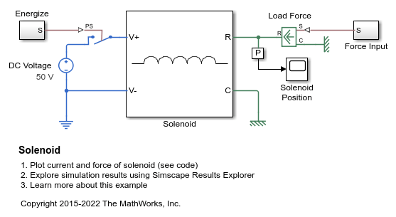
솔레노이드
이 예제는 스프링 복원력이 있는 솔레노이드를 보여줍니다. 솔레노이드는 플런저 위치 x에 따라 값 L이 달라지는 인덕턴스로 모델링됩니다. 시변 인덕턴스의 역기전력은 다음과 같습니다.
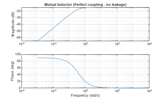
A Comparison of the Mutual Inductor and Ideal Transformer Library Blocks
The differences in behavior between the Mutual Inductor and Ideal Transformer blocks in the Simscape™ Foundation Library. These two blocks both represent the same system of electromagnetically-coupled windings but make different simplifying assumptions. It is important to understand the assumptions and how they impact model fidelity as a function of frequency. With this, you can make an informed decision about which block to use in a model of your circuit.

Operating Point RLC Transient Response
The response of a DC power supply connected to a series RLC load. The goal is to plot the output voltage response when a load is suddenly attached to the fully powered-up supply. This is done using a Simscape operating point.