addSensors
Description
addSensors(
adds the specified sensors from sensorSim,sensors,actorID)sensors to the vehicle actor with ID
actorID in the RoadRunner scenario associated with the SensorSimulation
object specified by sensorSim. Use this syntax when you define sensor
models in MATLAB®.
Note
If you modify the RoadRunner scene after creating the SensorSimulation object, you
must follow these steps for the changes to reflect correctly in MATLAB:
Save and close RoadRunner.
Clear the
ScenarioSimulationobject from the MATLAB workspace.Reopen the RoadRunner scenario.
Recreate the
ScenarioSimulationobject and theSensorSimulationobjects.
Examples
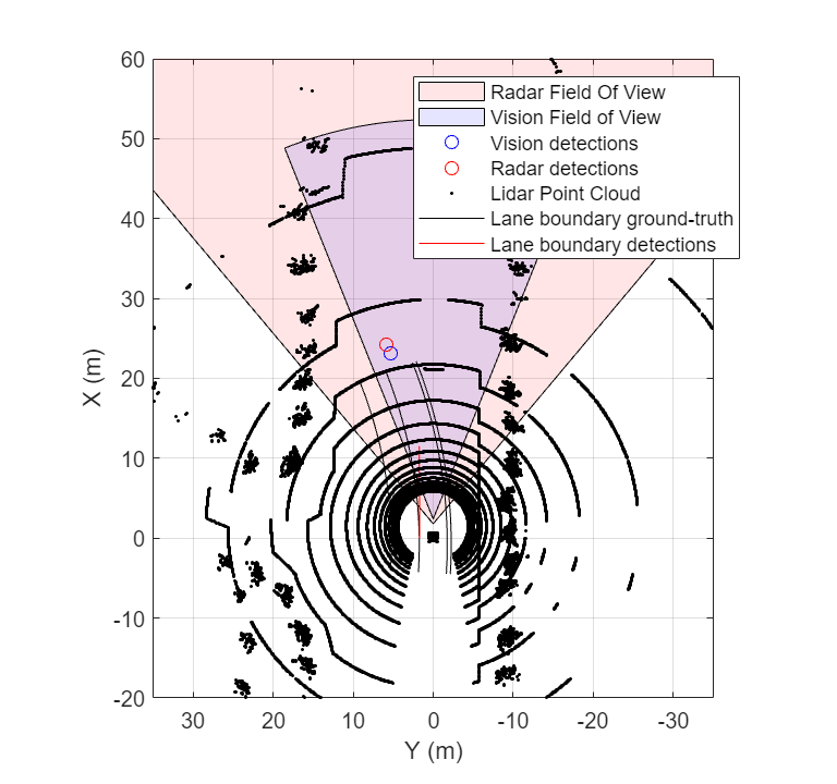
Define sensor models in MATLAB®, and add them to vehicle actors in a RoadRunner Scenario. Then, obtain ground truth measurements from RoadRunner Scenario, process them into detections for visualization.
Set Up RoadRunner Scenario — MATLAB Interface
Configure your RoadRunner installation and project folder properties. Open the RoadRunner app.
rrInstallationPath = "C:\Program Files\RoadRunner R2024a\bin\win64";
rrProjectPath = "D:\RR\TestProjects";

s = settings;
s.roadrunner.application.InstallationFolder.PersonalValue = rrInstallationPath;
rrApp = roadrunner(rrProjectPath);
To open the scenario this example uses, you must add the TrajectoryCutIn-longRun.rrscenario file from the example folder to your RoadRunner project folder. Then, open the scenario.
copyfile("TrajectoryCutIn-longRun.rrscenario",fullfile(rrProjectPath,"Scenarios/"))
openScenario(rrApp,"TrajectoryCutIn-longRun")
Create a ScenarioSimulation object to connect MATLAB to the RoadRunner Scenario simulation and set the step size.
scenarioSim = createSimulation(rrApp);
Connection status: 1
Connected to RoadRunner Scenario server on localhost:60730, with client id {761e01bc-376c-4b4b-8ffa-aa1490d7438d}
stepSize = 0.1;
set(scenarioSim,"StepSize",stepSize);
Create a SensorSimulation object to control the sensor configuration for the RoadRunner Scenario simulation.
sensorSim = get(scenarioSim,"SensorSimulation");To use the GPU on your device for supporting hardware accelerated raytracing, specify the UseGPU property of the SensorSimulation object to on. This enables supported sensors like lidars to use GPU for raytracing.
sensorSim.UseGPU = "on";
If you modify the RoadRunner scene after creating the SensorSimulation object, you must follow these steps for the changes to reflect correctly in MATLAB:
Save and close RoadRunner application.
Clear the
ScenarioSimulationobject from the MATLAB workspace.Reopen the RoadRunner scenario.
Recreate the
ScenarioSimulationobject and theSensorSimulationobject.
Configure Sensors and Add to RoadRunner Scenario
Configure sensor models for vision, radar and lidar sensors to add to the ego vehicle using visionDetectionGenerator, drivingRadarDataGenerator and lidarPointCloudGenerator objects. Specify unique IDs for each sensor.
visionSensor = visionDetectionGenerator(SensorIndex=1, ...
            SensorLocation=[2.4 0], MaxRange=50, ...
            DetectorOutput="Lanes and objects", ...
            UpdateInterval=stepSize);

radarSensor = drivingRadarDataGenerator(SensorIndex=2,...
    MountingLocation=[1.8 0 0.2], FieldOfView=[80 5],...
    AzimuthResolution=1,UpdateRate=1/stepSize);

lidarSensor = lidarPointCloudGenerator(SensorIndex=3,UpdateInterval=stepSize);
Add the sensor to the ego vehicle actor in the RoadRunner scenario. Specify the Actor ID property for the vehicle.
egoVehicleID = 1;
addSensors(sensorSim,{visionSensor,radarSensor,lidarSensor},egoVehicleID);
Simulate RoadRunner Scenario and Visualize Sensor Data
To visualize sensor data at each time-step of the simulation, add an observer to the RoadRunner scenario.
The helperSensorObserver system object implements the observer behavior. At the first timestep, the system object initializes the bird's-eye-plot for visualization, Then, at each time step, the system object:
Retrieves target poses in the sensor range using the
targetPosesfunction.Processes the target poses into detections using the sensor models.
Visualizes detections and ground truth lane boundaries using
birdsEyePlot.
observer = addObserver(scenarioSim,"VisualizeSensorData","helperSensorObserver");
Start the scenario.
set(scenarioSim,"SimulationCommand","Start");
Helper Functions
helperSetupBEP function creates a bird's-eye-plot and configures all the plotters for visualization.
helperPlotLaneBoundaries function plots the lane boundaries on the birds'eye-plot.
helperSensorObserver system object implements the visualization of sensor data during the RoadRunner scenario simulation.
type("helperSensorObserver.m")classdef helperSensorObserver < matlab.System
properties(Access=private)
currSimTime
scenarioSimObj
sensorSimObj
visionSensor
radarSensor
lidarSensor
visionDetPlotter
radarDetPlotter
pcPlotter
lbGTPlotter
lbDetPlotter
bepAxes
end
methods
% Constructor
function obj = helperSensorObserver()
end
end
methods(Access=protected)
function interface = getInterfaceImpl(~)
import matlab.system.interface.*;
interface = ActorInterface;
end
% Get ScenarioSimulation and SensorSimulation objects, set up Bird's-Eye-Plot
function setupImpl(obj)
obj.scenarioSimObj = Simulink.ScenarioSimulation.find('ScenarioSimulation','SystemObject',obj);
obj.sensorSimObj = obj.scenarioSimObj.get('SensorSimulation');
obj.visionSensor = evalin("base","visionSensor");
obj.radarSensor = evalin("base","radarSensor");
obj.lidarSensor = evalin("base","lidarSensor");
[obj.visionDetPlotter,obj.radarDetPlotter,obj.pcPlotter,obj.lbGTPlotter,obj.lbDetPlotter,obj.bepAxes] = helperSetupBEP(obj.visionSensor,obj.radarSensor);
legend(obj.bepAxes,"show")
obj.currSimTime = 0;
end
function releaseImpl(obj)
obj.lidarSensor.release;
obj.radarSensor.release;
obj.visionSensor.release;
end
function stepImpl(obj)
% Get current Simulation Time
obj.currSimTime = obj.scenarioSimObj.get("SimulationTime");
% Get ground truth target poses and lane boundaries from the sensor
tgtPoses1 = targetPoses(obj.sensorSimObj,1);
tgtPoses2 = targetPoses(obj.sensorSimObj,2);
gTruthLbs = laneBoundaries(obj.sensorSimObj,1,OutputOption="EgoAdjacentLanes",inHostCoordinate=true);
if ~isempty(gTruthLbs)
% Get detections from vision and radar sensors
[visionDets,numVisionDets,visionDetsValid,lbDets,numLbDets,lbDetsValid] = obj.visionSensor(tgtPoses1,gTruthLbs,obj.currSimTime);
[radarDets,numRadarDets,radarDetsValid] = obj.radarSensor(tgtPoses2,obj.currSimTime);
% Get point cloud from lidar sensor
[ptCloud,ptCloudValid] = obj.lidarSensor();
% Plot ground-truth and detected lane boundaries
helperPlotLaneBoundaries(obj.lbGTPlotter,gTruthLbs)
% Plot vision and radar detections
if visionDetsValid
detPos = cellfun(@(d)d.Measurement(1:2),visionDets,UniformOutput=false);
detPos = vertcat(zeros(0,2),cell2mat(detPos')');
plotDetection(obj.visionDetPlotter,detPos)
end
if lbDetsValid
plotLaneBoundary(obj.lbDetPlotter,vertcat(lbDets.LaneBoundaries))
end
if radarDetsValid
detPos = cellfun(@(d)d.Measurement(1:2),radarDets,UniformOutput=false);
detPos = vertcat(zeros(0,2),cell2mat(detPos')');
plotDetection(obj.radarDetPlotter,detPos)
end
% Plot lidar point cloud
if ptCloudValid
plotPointCloud(obj.pcPlotter,ptCloud);
end
end
end
end
end