uavSensor
Sensor for UAV scenario
Description
The uavSensor object creates a sensor that is rigidly attached to
a UAV platform, specified as a uavPlatform object.
You can specify different mounting positions and orientations. Configure this object to
automatically generate readings from a sensor specified as one of these System
objects.
gnssMeasurementGenerator(Navigation Toolbox)
Alternatively, you can specify a custom sensor that you derive from the uav.SensorAdaptor
class.
Creation
Description
sensor = uavSensor(name,platform,sensormodel)name and sensor model
sensormodel, which set the Name and
SensorModel properties respectively. The sensor is added to the
platform platform specified as a uavPlatform
object.
sensor = uavSensor(___,Name=Value)MountingLocation, MountingAngles,
or UpdateRate properties as name-value pairs. For example,
uavSensor("uavLidar",plat,lidarmodel,MountingLocation=[1 0 0])"
places the sensor one meter forward in the x-direction relative to
the platform body frame.
Properties
Object Functions
read | Gather latest reading from UAV sensor |
Examples
Create a scenario to simulate unmanned aerial vehicle (UAV) flights between a set of buildings. The example demonstrates updating the UAV pose in open-loop simulations. Use the UAV scenario to visualize the UAV flight and generate simulated point cloud sensor readings.
Introduction
To test autonomous algorithms, a UAV scenario enables you to generate test cases and generate sensor data from the environment. You can specify obstacles in the workspace, provide trajectories of UAVs in global coordinates, and convert data between coordinate frames. The UAV scenario enables you to visualize this information in the reference frame of the environment.
Create Scenario with Polygon Building Meshes
A uavScenario object is a model consisting of a set of static obstacles and movable objects called platforms. Use uavPlatform objects to model fixed-wing UAVs, multirotors, and other objects within the scenario. This example builds a scenario consisting of a ground plane and 11 buildings as by extruded polygons. The polygon data for the buildings is loaded and used to add polygon meshes.
% Create the UAV scenario.
scene = uavScenario(UpdateRate=2,ReferenceLocation=[75 -46 0]);

% Add a ground plane.
color.Gray = 0.651*ones(1,3);
color.Green = [0.3922 0.8314 0.0745];
color.Red = [1 0 0];
addMesh(scene,"polygon",{[-250 -150; 200 -150; 200 180; -250 180],[-4 0]},color.Gray)

% Load building polygons.
load("buildingData.mat");

% Add sets of polygons as extruded meshes with varying heights from 10-30.
addMesh(scene,"polygon",{buildingData{1}(1:4,:),[0 30]},color.Green)
addMesh(scene,"polygon",{buildingData{2}(2:5,:),[0 30]},color.Green)
addMesh(scene,"polygon",{buildingData{3}(2:10,:),[0 30]},color.Green)
addMesh(scene,"polygon",{buildingData{4}(2:9,:),[0 30]},color.Green)
addMesh(scene,"polygon",{buildingData{5}(1:end-1,:),[0 30]},color.Green)
addMesh(scene,"polygon",{buildingData{6}(1:end-1,:),[0 15]},color.Green)
addMesh(scene,"polygon",{buildingData{7}(1:end-1,:),[0 30]},color.Green)
addMesh(scene,"polygon",{buildingData{8}(2:end-1,:),[0 10]},color.Green)
addMesh(scene,"polygon",{buildingData{9}(1:end-1,:),[0 15]},color.Green)
addMesh(scene,"polygon",{buildingData{10}(1:end-1,:),[0 30]},color.Green)
addMesh(scene,"polygon",{buildingData{11}(1:end-2,:),[0 30]},color.Green)

% Show the scenario.
show3D(scene);
xlim([-250 200])
ylim([-150 180])
zlim([0 50])

Define UAV Platform and Mount Sensor
You can define a uavPlatform in the scenario as a carrier of your sensor models and drive them through the scenario to collect simulated sensor data. You can associate the platform with various meshes, such as fixedwing, quadrotor, and cuboid meshes. You can define a custom mesh defined ones represented by vertices and faces. Specify the reference frame for describing the motion of your platform.
Load flight data into the workspace and create a quadrotor platform using an NED reference frame. Specify the initial position and orientation based on loaded flight log data. The configuration of the UAV body frame orients the x-axis as forward-positive, the y-axis as right-positive, and the z-axis downward-positive.
load("flightData.mat")

% Set up platform
plat = uavPlatform("UAV",scene,ReferenceFrame="NED", ...
    InitialPosition=position(:,:,1),InitialOrientation=eul2quat(orientation(:,:,1)));

% Set up platform mesh. Add a rotation to orient the mesh to the UAV body frame.
updateMesh(plat,"quadrotor",{10},color.Red,[0 0 0],eul2quat([0 0 pi]))
You can choose to mount different sensors, such as the insSensor, gpsSensor, gnssMeasurementGenerator, or uavLidarPointCloudGenerator System objects to your UAV. Mount a lidar point cloud generator and a uavSensor object that contains the lidar sensor model. Specify a mounting location of the sensor that is relative to the UAV body frame.
lidarmodel = uavLidarPointCloudGenerator(AzimuthResolution=0.3324099,...
    ElevationLimits=[-20 20],ElevationResolution=1.25,...
    MaxRange=90,UpdateRate=2,HasOrganizedOutput=true);

lidar = uavSensor("Lidar",plat,lidarmodel,MountingLocation=[0,0,-1]);
Fly the UAV Platform Along Pre-Defined Trajectory and Collect Point Cloud Sensor Readings
Move the UAV along a pre-defined trajectory, and collect the lidar sensor readings along the way. This data could be used to test lidar-based mapping and localization algorithms.
Preallocate the traj and scatterPlot line plots and then specify the plot-specific data sources. During the simulation of the uavScenario, use the provided plotFrames output from the scene as the parent axes to visualize your sensor data in the correct coordinate frames.
Visualize the scene.
[ax,plotFrames] = show3D(scene);
Update plot view for better visibility.
xlim([-250 200])
ylim([-150 180])
zlim([0 50])
view([-110 30])
axis equal
hold on
Create a line plot for the trajectory. First create the plot with plot3, then manually modify the data source properties of the plot. This improves performance of the plotting.
traj = plot3(nan,nan,nan,Color=[1 1 1],LineWidth=2);
traj.XDataSource = "position(:,2,1:idx+1)";
traj.YDataSource = "position(:,1,1:idx+1)";
traj.ZDataSource = "-position(:,3,1:idx+1)";
Create a scatter plot for the point cloud. Update the data source properties again.
colormap("jet")
pt = pointCloud(nan(1,1,3));
scatterplot = scatter3(nan,nan,nan,1,[0.3020 0.7451 0.9333],...
    Parent=plotFrames.UAV.Lidar);
scatterplot.XDataSource = "reshape(pt.Location(:,:,1),[],1)";
scatterplot.YDataSource = "reshape(pt.Location(:,:,2),[],1)";
scatterplot.ZDataSource = "reshape(pt.Location(:,:,3),[],1)";
scatterplot.CDataSource = "reshape(pt.Location(:,:,3),[],1) - min(reshape(pt.Location(:,:,3),[],1))";
Set up the simulation. Then, iterate through the positions and show the scene each time the lidar sensor updates. Advance the scene, move the UAV platform, and update the sensors.
setup(scene)
for idx = 0:size(position, 3)-1
    [isupdated,lidarSampleTime, pt] = read(lidar);
    if isupdated
        % Use fast update to move platform visualization frames.
        show3D(scene,"Time",lidarSampleTime,FastUpdate=true,Parent=ax);
        % Refresh all plot data and visualize.
        refreshdata
        drawnow limitrate
    end
    % Advance scene simulation time and move platform.
    advance(scene);
    move(plat,[position(:,:,idx+1),zeros(1,6),eul2quat(orientation(:,:,idx+1)),zeros(1,3)])
    % Update all sensors in the scene.
    updateSensors(scene)
end
hold off

Create variables for the GNSS sample rate and the geodetic reference location. Set the sample rate to 10 Hz, and set the reference location to Natick, Massachusetts.
Fs = 10;
refLocNatick = [42.2825 -71.343 53.0352];
Create a UAV scenario using the specified reference location set to Natick, and set the update rate to match the GNSS sample rate.
scene = uavScenario(ReferenceLocation=refLocNatick,UpdateRate=Fs);
Create a UAV platform using the default NED reference frame.
plat = uavPlatform("UAV",scene,InitialPosition=[0 0 -30]);Create a gnssMeasurementGenerator object with the previously specified GNSS sample rate and reference location.
gnssSensor = gnssMeasurementGenerator(ReferenceLocation=refLocNatick, ...
    SampleRate=Fs);
Attach a GNSS sensor to the UAV platform using the uavSensor object, and specify gnssSensor as the sensor model.
gnss = uavSensor("GNSS",plat,gnssSensor,MountingLocation=[0 0 -0.5]);Set up the scenario, and get the initial pseudoranges, satellite positions, and satellite status measurements.
setup(scene)
[~,~,pr,satPos,status] = gnss.read
pr = 9×1
107 ×

    2.0592
    2.3883
    2.1700
    2.3951
    2.4177
    2.4169
    2.4096
    2.2914
    2.0648
satPos = 9×3
107 ×

   -0.1268   -2.1293    1.5824
    0.5893   -2.4783   -0.7515
    1.7686   -0.7116    1.8493
    1.3920    0.6196    2.1755
   -1.7465   -1.9452    0.4689
   -1.9616   -1.2167    1.3138
   -1.5231   -0.3071    2.1541
    1.3044   -2.2962   -0.2830
    1.3673   -1.3832    1.8087
status = struct with fields:
    LOS: [9×1 logical]
Advance the scene simulation time. The simulation advances a single step based on the specified update rate of 10 Hz, to 0.1 seconds.
advance(scene);
Update the sensors and get the pseudoranges, satellite positions, and satellite status measurements at the new timestep.
updateSensors(scene)
[isUpdated,timestamp,pr,satPos,status] = gnss.read
isUpdated = logical
   1
timestamp =
0.1000
pr = 9×1
107 ×

    2.0592
    2.3883
    2.1700
    2.3951
    2.4177
    2.4169
    2.4096
    2.2914
    2.0648
satPos = 9×3
107 ×

   -0.1268   -2.1293    1.5824
    0.5893   -2.4783   -0.7515
    1.7686   -0.7116    1.8493
    1.3920    0.6196    2.1755
   -1.7465   -1.9452    0.4689
   -1.9616   -1.2167    1.3138
   -1.5231   -0.3071    2.1541
    1.3044   -2.2962   -0.2830
    1.3673   -1.3832    1.8087
status = struct with fields:
    LOS: [9×1 logical]
Use the pseudoranges and satellite positions to estimate the UAV position. This result shows that the UAV is hovering 30 meters above the reference location.
recPos = receiverposition(pr(status.LOS,:),satPos(status.LOS,:))
recPos = 1×3

   42.2825  -71.3433   83.2265
Create a sensor adaptor for an imuSensor from Navigation Toolbox™ and gather readings for a simulated UAV flight scenario.
Create Sensor Adaptor
Use the createCustomSensorTemplate function to generate a template sensor and update it to adapt an imuSensor object for usage in UAV scenario.
createCustomSensorTemplate
This example provides the adaptor class uavIMU, which can be viewed using the following command.
edit uavIMU.m
Use Sensor Adaptor in UAV Scenario Simulation
Use the IMU sensor adaptor in a UAV Scenario simulation. First, create the scenario.
scenario = uavScenario("StopTime", 8, "UpdateRate", 100);
Create a UAV platform and specify the trajectory. Add a fixed-wing mesh for visualization.
plat = uavPlatform("UAV", scenario, "Trajectory", ...
    waypointTrajectory([0 0 0; 100 0 0; 100 100 0], "TimeOfArrival", [0 5 8], "AutoBank", true));
updateMesh(plat,"fixedwing", {10}, [1 0 0], eul2tform([0 0 pi]));
Attach the IMU sensor using the uavSensor object and specify the uavIMU as an input. Load parameters for the sensor model.
imu = uavSensor("IMU", plat, uavIMU(imuSensor));

fn = fullfile(matlabroot,'toolbox','shared',...
    'positioning','positioningdata','generic.json');
loadparams(imu.SensorModel,fn,"GenericLowCost9Axis");
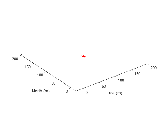
Visualize the scenario.
figure
ax = show3D(scenario);
xlim([-20 200]);
ylim([-20 200]);
Preallocate the simData structure and fields to store simulation data. The IMU sensor will output acceleration and angular rates.
simData = struct;
simData.Time = duration.empty;
simData.AccelerationX = zeros(0,1);
simData.AccelerationY = zeros(0,1);
simData.AccelerationZ = zeros(0,1);
simData.AngularRatesX = zeros(0,1);
simData.AngularRatesY = zeros(0,1);
simData.AngularRatesZ = zeros(0,1);
Set up the scenario.
setup(scenario);
Run the simulation using the advance function. Update the sensors and record the data.
updateCounter = 0;
while true
    % Advance scenario.
    isRunning = advance(scenario);
    updateCounter = updateCounter + 1;
    % Update sensors and read IMU data.
    updateSensors(scenario);
    [isUpdated, t, acc, gyro] = read(imu);
    % Store data in structure.
    simData.Time = [simData.Time; seconds(t)];
    simData.AccelerationX = [simData.AccelerationX; acc(1)];
    simData.AccelerationY = [simData.AccelerationY; acc(2)];
    simData.AccelerationZ = [simData.AccelerationZ; acc(3)];
    simData.AngularRatesX = [simData.AngularRatesX; gyro(1)];
    simData.AngularRatesY = [simData.AngularRatesY; gyro(2)];
    simData.AngularRatesZ = [simData.AngularRatesZ; gyro(3)];

    % Update visualization every 10 updates.
    if updateCounter > 10
        show3D(scenario, "FastUpdate", true, "Parent", ax);
        updateCounter = 0;
        drawnow limitrate
    end
    % Exit loop when scenario is finished.
    if ~isRunning
        break;
    end
end
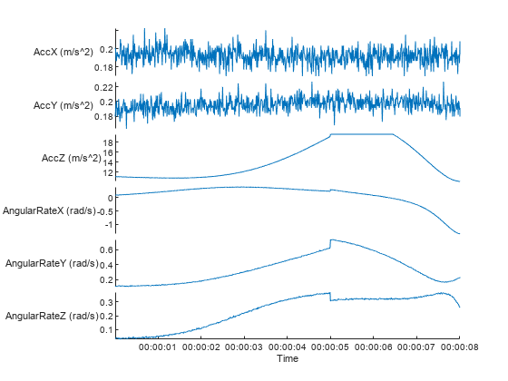
Visualize the simulated IMU readings.
simTable = table2timetable(struct2table(simData));
figure
stackedplot(simTable, ["AccelerationX", "AccelerationY", "AccelerationZ", ...
    "AngularRatesX", "AngularRatesY", "AngularRatesZ"], ...
    "DisplayLabels", ["AccX (m/s^2)", "AccY (m/s^2)", "AccZ (m/s^2)", ...
    "AngularRateX (rad/s)", "AngularRateY (rad/s)", "AngularRateZ (rad/s)"]);
Version History
Introduced in R2020bSee Also
Functions
Objects
uavScenario|uavPlatform|insSensor|gpsSensor|uavLidarPointCloudGenerator|uav.SensorAdaptor|gnssMeasurementGenerator(Navigation Toolbox)