컨버터(고전력)
예제를 통해 고전력 응용 분야(48V 이상)를 위한 컨버터를 모델링하는 방법을 알아봅니다.
추천 예제

Choose Strategy to Ground Converters with Isolated Topologies
Correctly ground isolated topologies, such as electrical power converters with galvanic isolation. You compare three methods of grounding an ideal transformer and choose the best option depending on your application.

모듈식 멀티레벨 컨버터를 사용하여 고전압 직류 전송 모델링하기
이 예제에서는 MMC(모듈식 멀티레벨 컨버터)를 사용하여 HVDC(고전압 직류) 전송을 모델링합니다.
18펄스 다이오드 정류기 모델링하기
이 예제에서는 선 전류의 고조파 감소를 위해 18펄스 다이오드 정류기를 모델링하는 방법을 보여줍니다.
24펄스 다이오드 정류기 모델링하기
이 예제에서는 선 전류의 고조파 감소를 위해 24펄스 다이오드 정류기를 모델링하는 방법을 보여줍니다.
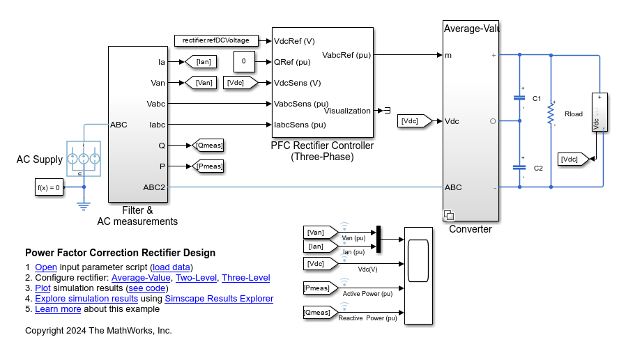
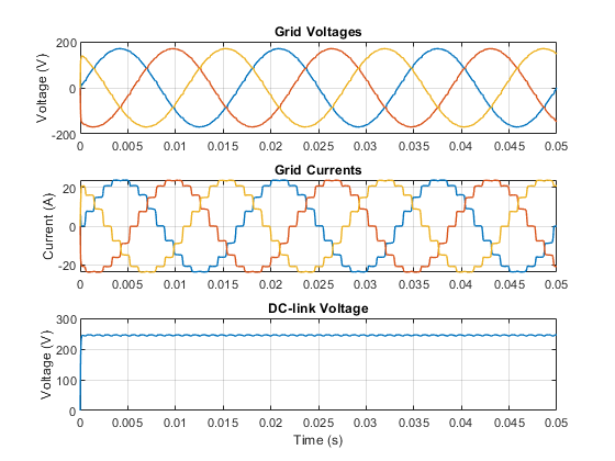
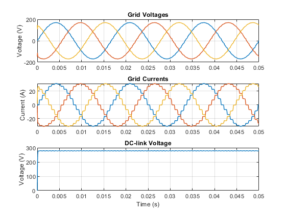
역률 개선 정류기 설계
이 예제에서는 3상 AC 공급 전압을 안정적인 DC 버스 전압으로 변환하고 그리드에서 끌어온 무효 전력을 제어하는 방법을 보여줍니다. 시스템에서 고조파를 줄이기 위해 PFC Rectifier Controller (Three-Phase) 블록을 사용하여 정현파 전류를 끌어옵니다.
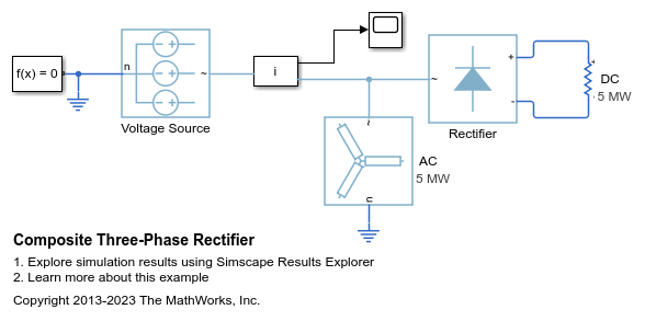
복합 3상 정류기
분석 워크플로 예제에 사용되는 기본 모델입니다.
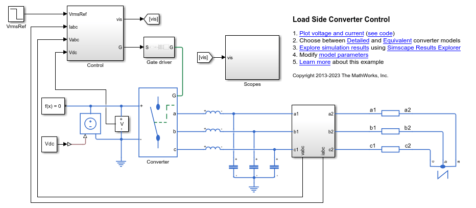
부하 측 컨버터 제어
이 예제에서는 부하 측 컨버터의 RMS 전압을 제어하는 방법을 보여줍니다. 부하는 3상 직렬 RL 요소에 의해 제공됩니다. Control 서브시스템은 2개의 제어 루프(바깥쪽의 전압 제어 루프와 안쪽의 전류 제어 루프)가 있는 PI 기반 캐스케이드 제어 구조를 사용합니다. 시뮬레이션은 스텝 기준 신호를 사용합니다. Scopes 서브시스템은 시뮬레이션 결과를 확인할 수 있는 스코프를 포함합니다.
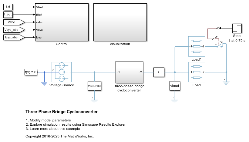
3상 브리지 사이클로컨버터
이 예제에서는 3상 브리지 사이클로컨버터를 보여줍니다. 사이클로컨버터는 36개의 사이리스터로 구성되며 입력 전압의 주파수를 낮출 수 있습니다. Control 서브시스템은 사이클로컨버터 RMS 전압 제어를 구현합니다. 또한 사이리스터 시동을 위한 펄스 생성도 제공합니다. Visualization 서브시스템은 시뮬레이션 결과를 확인할 수 있는 스코프를 포함합니다. 시뮬레이션 시간(t)은 1초입니다. t = 0.75초에서 Load1의 스위치가 켜지면 부하가 증가합니다.

3상 매트릭스 컨버터
이 예제에서는 정적 부하를 구동하고 소스에서 단위 역률을 이끌어 내는 3상 매트릭스 컨버터를 보여줍니다. Scopes 서브시스템은 시뮬레이션 결과를 확인할 수 있는 스코프를 포함합니다.
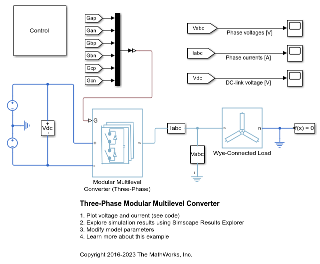
3상 모듈식 멀티레벨 컨버터
이 예제에서는 개루프 3상 모듈식 멀티레벨 컨버터(MMC: Modular Multilevel Converter)를 제어하는 방법을 보여줍니다. 각 MMC 암은 4개의 하프 브리지 하위 모듈로 구성됩니다. 와이 연결 직렬 RLC 구조가 시스템에 부하를 제공합니다.

Three-Phase Voltage-Sourced Converter (FLB)
Model a three-phase voltage-sourced converter that uses Fixed Low-side Bias (FLB) modulation. This modulation scheme minimizes the switching in the converter as at any given time one phase is not being pulse modulated. The trade-off is the need for narrower pulses for a given level of acceptable harmonics. The model can be used to support selection of suitable values for L, C and the pulse modulation scheme parameters.

3상 전압원 컨버터(SPWM)
이 예제에서는 정현파 펄스 폭 변조(SPWM: Sinusoidal Pulse-Width Modulation)를 사용하는 3상 전압원 컨버터를 모델링하는 방법을 보여줍니다. 이 변조 방식은 펄스를 생성하기 위해 기준 사인파와 고주파 반복 삼각파를 비교합니다. 다음 모델은 L, C, 펄스 변조 방식 파라미터에 적합한 값을 선택하는 데 사용할 수 있습니다.
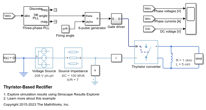
사이리스터 기반 정류기
이 예제에서는 사이리스터 기반 정류기를 보여줍니다.

토템폴 PFC
이 예제에서는 토템폴 PFC(역률 개선) 회로의 정류된 전압을 제어하는 방법을 보여줍니다. MOSFET Q1과 MOSFET Q2는 50kHz의 빠른 스위칭 레그를 형성합니다. MOSFET Q3과 MOSFET Q4는 선로 주파수의 느린 스위칭 레그를 형성합니다. Control 서브시스템은 PI 기반 캐스케이드 제어 구조를 사용합니다. Scopes 서브시스템은 시뮬레이션 결과를 확인할 수 있는 스코프를 포함합니다.

12펄스 사이리스터 정류기
이 예제에서는 12펄스 사이리스터 정류기를 제어하는 방법을 보여줍니다. 2개의 사이리스터 컨버터는 입력 측에서 와이-델타-와이 변압기에 연결됩니다. Thyristor 12-Pulse Generator 블록은 이 두 컨버터에 대해 게이트 신호를 생성합니다.

비엔나 정류기 제어
이 예제에서는 비엔나 정류기를 제어하는 방법을 보여줍니다. Vienna Rectifier 서브시스템은 3상 레그로 구성됩니다. 각 레그에는 1개의 전력 스위치와 6개의 전력 다이오드가 있습니다. Control 서브시스템은 공간 벡터 변조를 사용하여 비엔나 정류기에 대한 폐루프 제어 전략을 구현합니다. 총 시뮬레이션 시간은 0.1초입니다. 0.1초에 비엔나 정류기가 개입합니다. 0.4초와 0.6초에 DC 측에서 부하가 증가합니다.
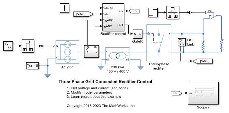
3상 전력망 연계형 정류기 제어
이 예제에서는 전력망 연계형 정류기를 사용하여 DC 링크 전압을 제어하는 방법을 보여줍니다. Rectifier control 서브시스템은 PI 기반 캐스케이드 제어 구조를 사용합니다. Scopes 서브시스템은 시뮬레이션 결과를 확인할 수 있는 스코프를 포함합니다. HDL Coder™에 대한 라이선스가 있는 경우 Simscape™ HDL Workflow Advisor를 사용하여 FPGA를 위한 VHDL 코드를 생성할 수 있습니다.
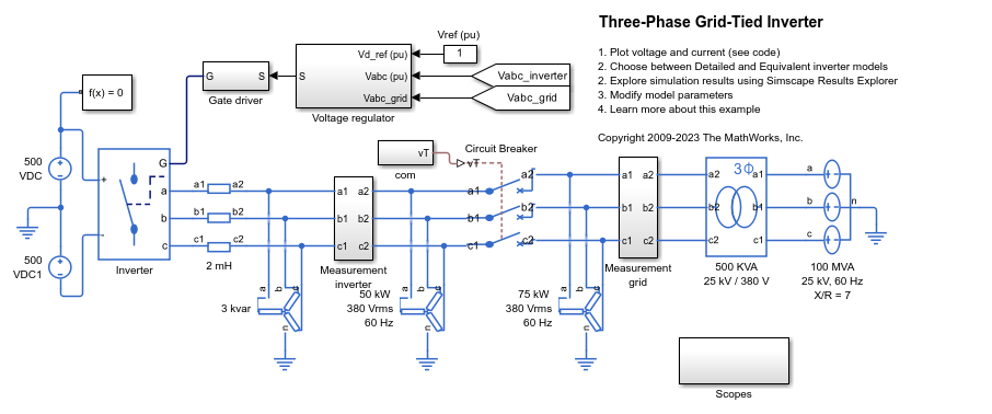
3상 계통 연계형 인버터
이 예제에서는 계통 연계형 인버터 시스템의 전압을 제어하는 방법을 보여줍니다. Voltage regulator 서브시스템은 PI 기반 제어 전략을 구현합니다. 3상 인버터는 회로 차단기를 통해 그리드에 연결됩니다. 회로 차단기는 동기화를 허용하도록 시뮬레이션 시작 시 열립니다. 시간 0.15초에서 회로 차단기는 닫히고 인버터가 그리드에 연결됩니다. Scopes 서브시스템은 시뮬레이션 결과를 확인할 수 있는 스코프를 포함합니다. 인버터는 IGBT를 사용하여 구현됩니다. 시뮬레이션의 속도를 높이거나 실시간 배포를 위해 IGBT를 평균 스위치로 대체할 수 있습니다. 이렇게 하면 게이트 신호를 지정된 기간 동안 평균화하거나 변조 파형으로 대체할 수 있습니다.

3상 계통 연계형 인버터 최적 전류 제어
이 예제에서는 계통 연계형 인버터 시스템의 전류를 제어하는 방법을 보여줍니다. Optimal controller 서브시스템은 관측기 기반 선형-2차 조절기 전략을 구현합니다. 제로 정상 상태 오류를 보장하기 위해 이 예제에서는 적분 동작에 대한 대안으로 관측기를 사용합니다. SPST 스위치가 3상 인버터를 그리드에 연결합니다. 이러한 스위치는 동기화를 허용하도록 시뮬레이션 시작 시 열립니다. 0.15초에서 인버터가 그리드에 연결됩니다. 그런 다음 0.2초에서 인버터는 그리드에 공급되는 유효 전력을 증가시킵니다. Scopes 서브시스템은 시뮬레이션 결과를 확인할 수 있는 스코프를 포함합니다. 인버터는 Ideal Semiconductor Switch 블록을 사용하여 구현됩니다. HDL Coder™에 대한 라이선스가 있는 경우 Simscape™ HDL Workflow Advisor를 사용하여 FPGA를 위한 VHDL 코드를 생성할 수 있습니다.
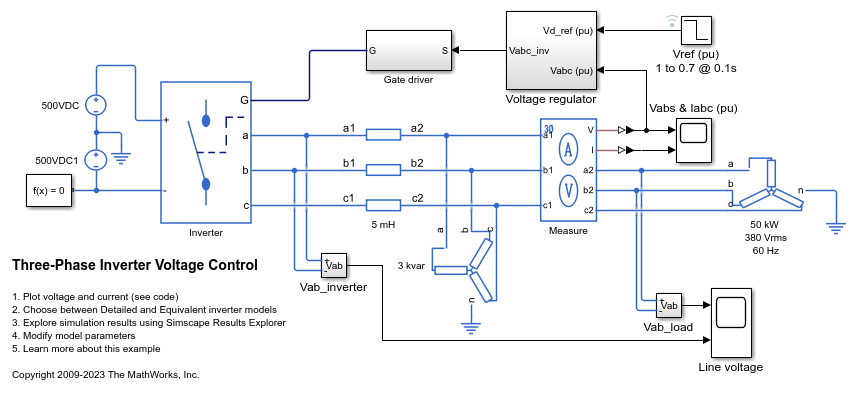
3상 인버터 전압 제어
이 예제에서는 3상 인버터 시스템의 전압을 제어하는 방법을 보여줍니다. 인버터는 IGBT를 사용하여 구현됩니다. 시뮬레이션의 속도를 높이거나 실시간 배포를 위해 IGBT를 평균 스위치로 대체할 수 있습니다. 이렇게 하면 게이트 신호를 지정된 기간 동안 평균화하거나 변조 파형으로 대체할 수 있습니다.
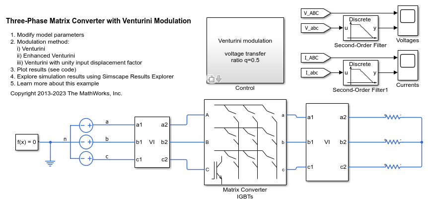
Three-Phase Matrix Converter with Venturini Modulation
Use Venturini modulation techniques to compute the duty cycles and logic statements of a three-phase matrix converter that drives a static load. The control subsystem implements three different modulation algorithms: Venturini modulation, third harmonic enhanced Venturini modulation, and third harmonic injection Venturini modulation with unity input displacement factor. The maximum voltage transfer ratio between input and output depends on the modulation technique and it is equal to either q=0.5 or q=0.866. The Scope blocks show the voltages and currents V_ABC, V_abc, I_ABC, and I_abc, where _UPPERCASE is used for inputs and _LOWERCASE for outputs.

이중 액티브 브리지 제어
이 예제에서는 이중 액티브 브리지 DC-DC 컨버터의 출력 전압을 제어하는 방법을 보여줍니다. 각 스위치는 해당 스위칭 주기의 50% 동안 켜져 있습니다. 위상 변위 제어기는 출력 브리지에서 가변적인 위상 변위를 발생시키고 출력 전압을 제어합니다. 입력 전압과 시스템 부하는 시뮬레이션 과정 전체에서 일정하게 유지됩니다. 총 시뮬레이션 시간(t)은 0.25초입니다. t = 0.15초에서 전압 기준이 변경됩니다.

전기차 V2G(Vehicle-to-Grid) 지원을 사용한 마이크로그리드
이 예제에서는 EV(전기차)의 V2G(Vehicle-to-Grid) 지원을 사용하여 마이크로그리드를 모델링하는 방법과 마이크로그리드의 주파수를 조절하는 방법을 보여줍니다.

Manage Model Fidelity Using Variants
Compare and contrast modeling different fidelity levels by using variants. The controller model uses a Variant Source block configured in Expression mode. The plant model uses a Variant Subsystem.
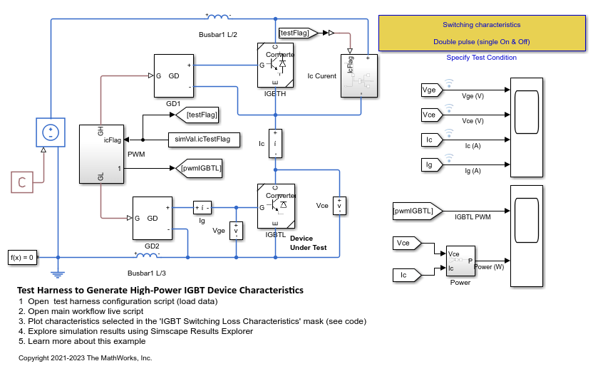
Test Harness to Generate High-Power IGBT Device Characteristics
Provides test harness for estimating switching loss for different parameters of a N-Channel IGBT block.

Test Harness to Generate IV Characteristics of N-Channel IGBT
Provides test harness for estimating current-voltage characteristics of a N-Channel IGBT.

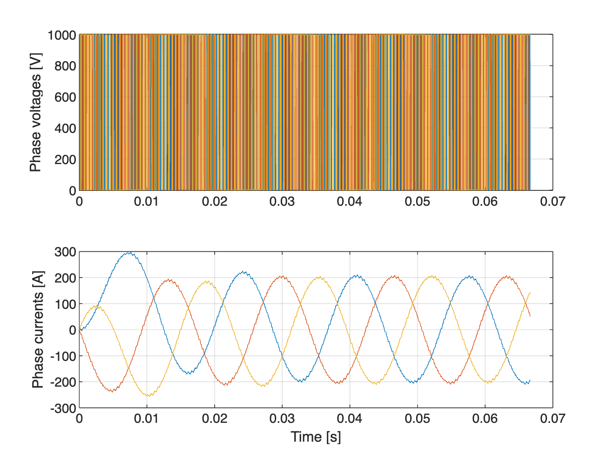
Three-Phase High-Power Converter Design and Analysis Workflow
The main steps involved in designing a high-power converter. High power converters are important building blocks for future electric mobility and microgrid solutions. To design a cost effective, lightweight, efficient converter, you must perform detailed analysis of different converter design options and deployment scenarios. This example helps you to simulate the steady state, transient electrical, and thermal characteristics of a three-phase two-level converter that uses Insulated-Gate Bipolar Transistor (IGBT) devices.

Fault Detection of Electric Vehicle Charger
Analyzes the fault of an electric vehicle (EV) charger using Simscape™ Electrical™ to model the grid, the converter, and its control unit. The reliability of these chargers is an important factor in their adoption. In this example, you use measurements from the grid and the DC side of the converter to detect a gate driver fault in the converter. To analyze and detect a fault, first you generate synthetic data for different conditions with and without faults. Then you use this data to train a classification algorithm using the 분류 학습기 (Statistics and Machine Learning Toolbox). Finally, you use the trained model to identify or detect faults in any phase and to generate the code for deployment on hardware. You can extend this model for other system level variations or noises by having a much larger and comprehensive training dataset.
Optimize Liquid Cooling System of Inverter
Analyze the performance of a liquid cooling system for a three-phase inverter. To find the steady-state temperatures and losses, you first run detailed and reduced order models (ROM). Then you compute the optimal size of the heatsink that maximizes the inverter efficiency and minimizes the lifetime cost.

High-Voltage, Direct-Current Transmission Using Voltage Source Converters
Models a high-voltage, direct-current (HVDC) transmission system using voltage source converters (VSCs).