단계별로 로봇 빌드하기
이 예제는 로봇을 빌드하는 과정을 단계별로 진행하면서 로봇의 여러 컴포넌트를 소개하고 로봇을 빌드하기 위해 함수를 호출하는 방법을 보여줍니다. 예제에서 코드 섹션이 함께 제공되지만, 실제 차원 값과 변환 값은 로봇에 따라 달라집니다.
rigid body 객체를 만듭니다.
body1 = rigidBody('body1');
조인트를 만들어 강체에 할당합니다. 조인트의 홈 위치 속성
HomePosition을 정의합니다. 동차 변환tform을 사용하여 조인트-부모 변환을 설정합니다.trvec2tform함수를 사용하여 평행 이동 벡터에서 동차 변환으로 변환합니다.ChildToJointTransform은 단위 행렬로 설정됩니다.jnt1 = rigidBodyJoint('jnt1','revolute'); jnt1.HomePosition = pi/4; tform = trvec2tform([0.25, 0.25, 0]); % User defined setFixedTransform(jnt1,tform); body1.Joint = jnt1;

강체 트리를 만듭니다. 이 트리는 바디를 연결할 베이스 좌표 프레임으로 초기화됩니다.
robot = rigidBodyTree;
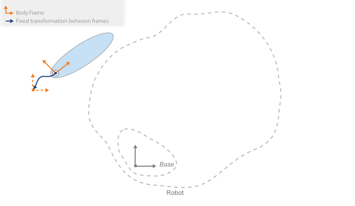
트리에 첫 번째 바디를 추가합니다. 바디가 트리의 베이스에 연결되도록 지정합니다. 앞에서 정의한 고정 변환은 베이스(부모)에서 첫 번째 바디까지입니다.
addBody(robot,body1,'base')
두 번째 바디를 만듭니다. 이 바디의 속성을 정의하고 첫 번째 강체에 연결합니다. 앞에서 설정된 바디 프레임을 기준으로 변환을 정의합니다.
body2 = rigidBody('body2');
jnt2 = rigidBodyJoint('jnt2','revolute');
jnt2.HomePosition = pi/6; % User defined
tform2 = trvec2tform([1, 0, 0]); % User defined
setFixedTransform(jnt2,tform2);
body2.Joint = jnt2;
addBody(robot,body2,'body1'); % Add body2 to body1

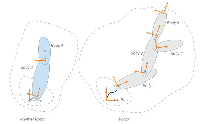
다른 바디들을 추가합니다. 바디 2에 바디 3과 바디 4를 연결합니다.
body3 = rigidBody('body3');
body4 = rigidBody('body4');
jnt3 = rigidBodyJoint('jnt3','revolute');
jnt4 = rigidBodyJoint('jnt4','revolute');
tform3 = trvec2tform([0.6, -0.1, 0])*eul2tform([-pi/2, 0, 0]); % User defined
tform4 = trvec2tform([1, 0, 0]); % User defined
setFixedTransform(jnt3,tform3);
setFixedTransform(jnt4,tform4);
jnt3.HomePosition = pi/4; % User defined
body3.Joint = jnt3
body4.Joint = jnt4
addBody(robot,body3,'body2'); % Add body3 to body2
addBody(robot,body4,'body2'); % Add body4 to body2

제어해야 하는 특정 엔드 이펙터가 있는 경우 고정 조인트가 있는 강체로 정의합니다. 이 로봇의 경우
body4에 엔드 이펙터를 추가하여 이 바디의 엔드 이펙터에 대한 변환을 구할 수 있습니다.bodyEndEffector = rigidBody('endeffector'); tform5 = trvec2tform([0.5, 0, 0]); % User defined setFixedTransform(bodyEndEffector.Joint,tform5); addBody(robot,bodyEndEffector,'body4');
로봇을 만들었으니 이제 로봇 컨피규레이션을 생성할 수 있습니다. 컨피규레이션이 주어지면
getTransform을 사용하여 두 바디 프레임 사이의 변환을 구할 수도 있습니다. 엔드 이펙터에서 베이스까지의 변환을 구합니다.config = randomConfiguration(robot) tform = getTransform(robot,config,'endeffector','base')
config =

  1×2 struct array with fields:

    JointName
    JointPosition


tform =

   -0.5484    0.8362         0         0
   -0.8362   -0.5484         0         0
         0         0    1.0000         0
         0         0         0    1.0000
참고
이 변환은 이 예제에서 지정한 차원에 한정됩니다. 로봇에 대한 값은 사용자가 정의하는 변환에 따라 달라집니다.
subtree를 사용하여 기존 로봇 모델 또는 다른 로봇 모델로부터 하위 트리를 만들 수 있습니다. 새로운 하위 트리의 베이스로 사용할 바디 이름을 지정합니다. 바디를 추가, 변경, 제거하여 이 하위 트리를 수정할 수 있습니다.newArm = subtree(robot,'body2'); removeBody(newArm,'body3'); removeBody(newArm,'endeffector')
이러한 하위 트리를 로봇에 추가할 수도 있습니다. 하위 트리를 추가하는 방법은 바디를 추가하는 방법과 유사합니다. 지정한 바디 이름은 연결을 위한 베이스가 되며, 하위 트리의 모든 변환은 해당 바디 프레임을 기준으로 합니다. 하위 트리를 추가하기 전에 바디와 조인트의 모든 이름이 고유한지 확인해야 합니다. 바디와 조인트의 복사본을 만들고 이름을 변경한 후 하위 트리에서 이들로 대체합니다.
addSubtree를 호출하여 지정된 바디에 하위 트리를 연결합니다.newBody1 = copy(getBody(newArm,'body2')); newBody2 = copy(getBody(newArm,'body4')); newBody1.Name = 'newBody1'; newBody2.Name = 'newBody2'; newBody1.Joint = rigidBodyJoint('newJnt1','revolute'); newBody2.Joint = rigidBodyJoint('newJnt2','revolute'); tformTree = trvec2tform([0.2, 0, 0]); % User defined setFixedTransform(newBody1.Joint,tformTree); replaceBody(newArm,'body2',newBody1); replaceBody(newArm,'body4',newBody2); addSubtree(robot,'body1',newArm);
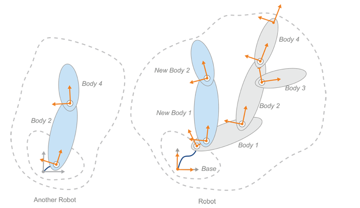
마지막으로
showdetails를 사용하여 빌드한 로봇을 살펴볼 수 있습니다. 조인트 유형이 올바른지 확인하십시오.showdetails(robot)
 Idx          Body Name             Joint Name             Joint Type          Parent Name(Idx)   Children Name(s)
 ---          ---------             ----------             ----------          ----------------   ----------------
   1              body1                   jnt1               revolute                   base(0)   body2(2)  newBody1(6)
   2              body2                   jnt2               revolute                  body1(1)   body3(3)  body4(4)
   3              body3                   jnt3               revolute                  body2(2)
   4              body4                   jnt4               revolute                  body2(2)   endeffector(5)
   5        endeffector        endeffector_jnt                  fixed                  body4(4)
   6           newBody1                newJnt1               revolute                  body1(1)   newBody2(7)
   7           newBody2                newJnt2               revolute               newBody1(6)
--------------------
참고 항목
rigidBodyTree | inverseKinematics