주요 콘텐츠

Visualize Point Cloud Using Color and Camera Views

R2026b

The Point Cloud Analyzer app provides various colors and camera view options to analyze point cloud data. From the Data Browser pane, select the point cloud that you want to visualize. For information on how to open the Point Cloud Analyzer app and import data, see Import, View, and Export Point Cloud.

Color Controls
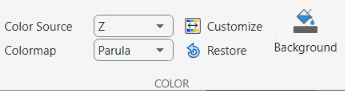
Color section on app toolstrip

You can control the color of the displayed point cloud by using the options in the Color section of the app toolstrip:

Specify the attribute for coloring points as one of these values:

  • X — Color the points based on the x-coordinate values of the input point cloud.

  • Y — Color the points based on the y-coordinate values of the input point cloud.

  • Z — Color the points based on the z-coordinate values of the input point cloud.

  • Color Attribute — Color the points using the Color values of the input point cloud. This option is available only when the input point cloud has color information.

  • Intensity — Color the points using the Intensity values of the input point cloud. This option is available only when the input point cloud contains intensity values.

  • Row — Color the points using their row indices. This option is available only for organized point clouds.

  • Column — Color the points using their column indices. This option is available only for organized point clouds.

  • Single Color — Color all points using a single color.

When you select Custom color source button, the app opens the Customize Color dialog box where you can select linear, logarithmic, exponential, or sigmoid variation. When you select Linear, the color variation is linear along the axis you select for the Color Source of the point cloud.

You can also modify the color variation by using the color bar.

Custom color variation

Choose the color profile for the point cloud data from one of these options. Click the restore arrow to reset the selection to Parula.

  • Parula

  • Hot

  • Spring

  • Turbo

  • Nebula

For more details, see colormap.

Note

You cannot use Colormap when Color Source is Color Attribute or Single Color.

Select the background color for the point cloud display.

Camera Controls

Camera section on app toolstrip

The app provides various predefined camera angles for viewing the point cloud data. You can also save and organize views.

Note

A Windows® OS machine must have WebGL™ 2 support for graphics rendering.

The orthographic projection type maintains the correct relative dimensions of graphics objects regarding the distance of a given point from the viewer. Relative distance from the camera does not affect the size of objects. Lines that are parallel in the data parallel appear parallel on the screen. This projection type is useful when it is important to maintain the actual size of objects and the angles between objects.

The Perspective projection projects the viewing volume as the frustum of a pyramid (a pyramid whose apex has been cut off parallel to the base). Objects further from the camera appear smaller. Distance causes foreshortening, which enables you to perceive the depth of 3-D objects. This projection type is useful when you want to display realistic views of real objects. Perspective projection does not preserve the relative dimensions of objects. Instead, it displays a distant line segment smaller than a nearer line segment of the same length. Lines that are parallel in the data might not appear parallel in the scene.

To visualize point cloud data in a 2-D plane, click Planar Views and select a 2-D plane from these options:

  • XY — View the xy-axes of a point cloud. This is the top view of the scene, and line of sight is along the z-axis.

  • YX — View the yx-axes of a point cloud. This view is the mirror image of the XY View with respect to the y-axis.

  • YZ — View the yz-axes of a point cloud. This is the front view of the scene, and line of sight is along the x-axis.

  • ZY — View the yz-axes of a point cloud. This view is the mirror image of the YZ with respect to the z-axis.

  • XZ — View the xz-axes of a point cloud. This is a side view of the scene, and line of sight is along the y-axis.

  • ZX — View the zx-axes of a point cloud. This view is the mirror image of the XZ with respect to the z-axis.

The app provides orbital and first-person navigation controls. These controls describe the behavior of the observer or first person, represented as the camera, with respect to the object to visualize or orbital, represented as the target.

  • Orbital — Camera target is fixed. Only the camera position can change.

  • First person — Both the camera position and the target position can change. Enables first-person navigation for the perspective camera projection.

Note

The app enables first-person navigation for the perspective camera projection only.

This table lists the mouse interactions for the Orbital and First person camera controls:

InteractionOrbitalFirst person
RotateRotate the object around the observerObserver rotates. (Looks around the scene.)
PanPan the object with respect to the observerObserver moves or "walks" through the scene in the left, right, up, or down directions.
ZoomZoom object toward or away from observer. (Make the object appear larger or smaller).Observer moves or "walks" in the forward or backward directions.

This table shows the orbital keyboard shortcuts:

BehaviorKeyboard shortcut
Rotate by Z-axisLeft and right arrows
Rotate by X-axisUp and down arrows
Rotate by Y-axisQ and E

This table shows the first-person keyboard shortcuts:

BehaviorKeyboard Shortcut
Move forward

W — Forward

S — Backward

Move left or right

A — Left

D — Right

Move up or down

R — Up

F — Down

Look around the scene (Pitch/Yaw rotation of camera)

Up arrow — Pitch up

Down arrow — Pitch down

Left arrow — Yaw left

Right arrow — Yaw right

Roll the scene (Roll rotation of camera)

Q — Clockwise roll

E — Counter-clockwise roll

The app enables you to rotate a point cloud for orbital navigation. Select any point as the center of rotation. When the Rotate Around Point is disabled, the center of rotation is the axes center. The Rotate Around Point mode can only be used with the Orbital Navigation mode.

View from a high angle above a point cloud.

Bird's Eye View of a driving scene

View the point cloud from a fixed distance behind the ego vehicle (actor). You can specify the ego direction by using the drop down.

Chase View of a driving scene

View a point cloud from the perspective of the ego vehicle. You can specify the ego direction by using the drop down.

Ego View of a driving scene

To save a view, click Custom View > Save Camera View, specify a name for the view, and click OK. You can return to the saved view at any time by clicking Custom View and then selecting the view from the Saved Camera Views list, which appears after a view is saved. To delete or rename saved views, click Custom View > Manage Camera Views.

Tip

You can adjust the point cloud view by using the x-, y-, z-axes at the bottom left corner of the visualization pane.

Rotate point cloud using point cloud axes

Size

Size section of toolstrip

Adjust the display size of the points by specifying the Point Size. For the first-person navigation using perspective projection, you can enlarge the points for better visualization. When you select Magnify Points, you can attenuate the size of the points based on the camera position. If the camera is positioned closer to the points, the points appear bigger than when the camera is far away. The Magnify Points option applies only for the perspective camera projection and the first person controls.

Segment

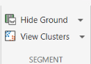
Segment section of toolstrip

The app provides options to hide the ground and to view point cloud clusters.

Select Hide Ground to remove ground points from the point cloud. This enables the Ground Settings option. Click Ground Settings to open a dialog box in which you can select from these ground removal algorithms and specify their parameters.

  • Segment ground SMRF (default) — Segment the ground points using the segmentGroundSMRF function.

  • Fit ground plane — Fit and filter the ground plane using the pcfitplane function.

  • Range-based floodfill — Remove ground points using the segmentGroundFromLidarData function. The app enables this option for only organized point clouds.

To visualize the segmented ground and nonground planes on the point cloud, select View Ground Data.

Select View Clusters to view point cloud clusters. To adjust cluster settings at any time while using the app, click Cluster Settings, which opens the Cluster Settings dialog box. In this dialog box, you can select one of these cluster-based coloring algorithms and set its parameters.

  • Range-based clustering — Select this algorithm to cluster point cloud data using the segmentLidarData function. This option is not applicable for unorganized point cloud data.

  • Distance-based clustering — Select this algorithm to cluster point cloud data using the pcsegdist function.

See Also

Apps

Topics