Simulating Back-EMF Voltage of a BLDC Motor | How to Design Motor Controllers Using Simscape Electrical, Part 1
From the series: How to Design Motor Controllers Using Simscape Electrical
Melda Ulusoy, MathWorks
This video demonstrates how you can model a three-phase BLDC motor using Simscape Electrical™ and investigate its back-EMF profile.
Download the model used in this video.
Check out this video to learn more about brushless DC motors
Published: 8 Aug 2019
In this video, we’ll create a simple model to simulate a three-phase BLDC and investigate its back-EMF profile. In Simulink, we’ll create a scenario where we turn the motor shaft while having open terminals at all three phases and then measure the voltage produced at one of the phases to observe the back-EMF.
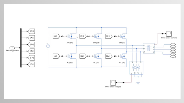
We will now create a physical model to simulate this scenario using Simscape Electrical. In the Simulink library browser, we first navigate to the Permanent Magnets and drag the BLDC block to the canvas. This block represents a BLDC with a trapezoidal back-EMF profile. You can use your motor’s data sheet to set the values of the block parameters under the rotor, stator and mechanical tabs. In the later videos, we’ll talk about the parameterization in more detail. The ports at the left-hand side of the block are for electrical connections and the ones on the right are for the mechanical connections.
To create open terminals, we first expand the composite port to three phases and then connect an open circuit block to each of the phases. To connect the motor’s neutral phase to the ground, we use the electrical reference block.
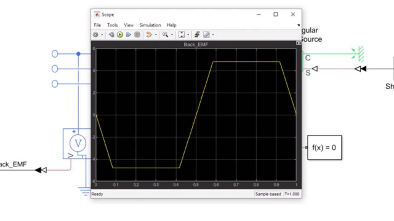
Now we’re going to work on the mechanical connections of the motor. To make the motor shaft turn, the motor is driven by using an ideal angular velocity source block. You can think of this block as a torque source that will make the rotor follow a specified angular trajectory. We then connect a mechanical reference to the ports labeled with C. The velocity source block has a second input, which is a physical signal. In order to make the motor rotate at a constant speed, we’ll input a constant value to the block. This block outputs a Simulink signal. We need to convert it to a physical signal by using the Simulink PS converter. To solve the Simscape model we just created, we use a solver block where we choose to use the local solver and also set the sample time. We’ll discuss how to choose a sample time in a later video. Now we can simply pick one of the three phases and measure the back-EMF. Let’s connect a voltage sensor to phase A to measure phase A’s back-EMF voltage. The output of the voltage sensor block is a Simscape signal. In order to convert it to a Simulink signal, this time we use PS Simulink converter and connect the signal to a scope for visualization. Then we simulate this model and view the back-EMF voltage of phase A. We observe that the back-EMF exhibits a trapezoidal shape, including regions where the voltage remains flat. This concludes the video.
Download Code and Files
Related Products
Learn More


웹사이트 선택
번역된 콘텐츠를 보고 지역별 이벤트와 혜택을 살펴보려면 웹사이트를 선택하십시오. 현재 계신 지역에 따라 다음 웹사이트를 권장합니다: United States
또한 다음 목록에서 웹사이트를 선택하실 수도 있습니다.
미주
- América Latina (Español)
- Canada (English)
- United States (English)
유럽
- Belgium (English)
- Denmark (English)
- Deutschland (Deutsch)
- España (Español)
- Finland (English)
- France (Français)
- Ireland (English)
- Italia (Italiano)
- Luxembourg (English)
- Netherlands (English)
- Norway (English)
- Österreich (Deutsch)
- Portugal (English)
- Sweden (English)
- Switzerland
- United Kingdom (English)