Position Tracking for X-Configuration Quadcopter Using Rate Controller
This example shows how to use the UAV Toolbox Support Package for PX4® Autopilots to design a position controller using rate control for an X-configuration quadcopter. In this example, you also verify the controller design using the PX4 Host Target and jMAVSim simulator.
Introduction
UAV Toolbox Support Package for PX4 Autopilots enables you use Simulink® to design flight controller algorithm to stabilize the vehicle based on the current vehicle attitude, position and velocity, and also track the desired attitude using Simulink.
In this example, you will learn how to use the PX4 Host Target and jMAVSim simulator to design and verify position and velocity controller for X-configuration quadrotor vehicle and control the vehicle position using various sliders, available in Simulink model. The jMAVSim simulator, which is part of the Software In The Loop (SITL) simulation as defined in PX4 website and is installed as part of the support package installation.
Prerequisites
If you are new to Simulink, watch the Simulink Quick Start video.
Perform the initial Setup and Configuration of the support package using Hardware Setup screens. In the Hardware Setup screen Select a PX4 Autopilot and build configuration, select PX4 Host Target as the Hardware board from the drop-down list.

Model
Open the px4demo_PositionAndRateController model.

The model implements a Proportional-Integral-Derivative (PID) controller to control the position, velocity and attitude of an X-configuration quadrotor aerial vehicle. At each time step, the algorithm adjusts rotational speeds of different rotors to track the desired attitude, depicted by the velocity error.
Task 1 - Read Desired Position and Current Position
In this example, we consider the influence of wind gust on the quadcopter while it is flying. The quadcopter must try to maintain the desired position and altitude. According to the error in position, the pitch and roll commands are generated and the output to the actuator motors are modified.
The Input Sliders in the model can be used to provide the desired coordinates of the flight of the quadcopter.

The variable des_alt represents an altitude at which the vehicle hovers. The altitude value can be set using the respective slider or directly changing the value of constant des_alt.
The desired position for X and Y can be set by assigning desired values to constants des_x and des_y or using respective sliders.
In the Desired Position, Altitude and Yaw area, you can also provide dynamic inputs (instead of only static inputs) to test the tracking capabilities of the position controller. In this example, the sine wave is used as the dynamic input and can be selected using respective manual switches.

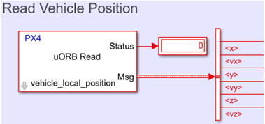
The vehicle's position in the NED reference frame and its rates can be accessed using uORB Read block, which is configured to read the message 'vehicle_local_position'.

Task 2 - Design Position and Velocity Controller

In the Position & Altitude Control subsystem, three separate PID blocks utilize the difference between the desired and current value to generate the requirement for x and y velocities. The output of each PID block is restricted between predefined maximum and minimum values to limit velocities. For this example, the limit is set at 20 m/s in x & y direction, and 10 m/s for altitude. The maximum limits of velocities are usually inferred from vehicle characteristics.
For a particular vehicle, maximum achievable translation velocities depend on limits of pitch and roll angles. The pitch and roll angles are restricted up to 50 degrees for the simulated vehicle. The limits of achievable translation velocities can be set by manually giving maximum pitch / roll stick input in the example 'px4demo_AttitudeControllerWithJoystick_quadrotor' and observing x & y velocities.
The maximum rate of climb of the vehicle is primarily dependent on the performance of the propulsion system and the mass of the vehicle. For the simulated vehicle, the maximum rate of climb can be set by manually giving maximum throttle stick input in the example 'px4demo_AttitudeControllerWithJoystick_quadrotor' and observing z velocity.
Since the velocities are measured in the NED reference frame, the current velocity error is computed first before applying the correction for the non-zero yaw angle via the rotation matrix.
The corrected velocity error is fed to separate PIDs to generate the requirement for rotation angles, pitch and roll. An output of each PID block is restricted between predefined maximum and minimum values to limit roll and pitch angles.
The rest of the design for attitude controller and mixer is similar to the example 'Position Tracking for X-Configuration Quadcopter'.
Task 3 - Tune PID Using Monitor and Tune
For instructions to build the model and perform Monitor and Tune operation with data monitoring, refer to the example 'px4demo_AttitudeControllerWithJoystick_quadrotor'.
When you start Monitor and Tune, the jMaVSim simulator is also launched.
For more details about tuning the controller using PID, refer to the example 'Position Tracking for X-Configuration Quadcopter'.
Advantages of the Present Controller over the Position-Only Control
As observed in the example 'Position Tracking for X-Configuration Quadcopter', for a vast range of input signals, uniform system response cannot be achieved by the position control only. For a step input of 20m and 50m respectively, the system has a different response.
This behavior comes from the fact that for a quadrotor vehicle, we cannot control the position directly. The manipulated or control variable in a quadrotor is the rotational speed of four rotors. The difference in rotational speeds results in a difference in thrust and this asymmetrical thrust generates a moment around various axes. The moment induces angular rates, which changes vehicle attitude (that is, roll, pitch and yaw angles). Non-zero pitch and roll angles generate translation velocities, due to which finally the quadrotor position changes.
In only position control, we are trying to control the vehicle position while changing rotational speeds of four rotors. There is a huge time delay between the moment at which changes are made in rotational speed and the moment at which the effect of the change in rotational speed observed in the vehicle position. This delay in propagation of vehicle dynamics usually results in an overshoot.
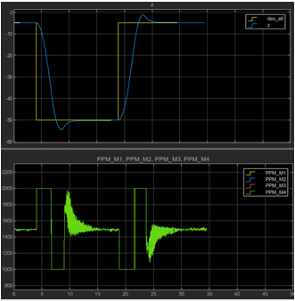
With the addition of a velocity controller in between the position controller and attitude controller, this delay reduces and the controller performance can be improved. Figure C and Figure D show the response of the vehicle to step input of 20m and 50m respectively with rate control. Here, the vehicle has the same response to both inputs without considerable overshoot.

Improvement in the controller performance can be easily observed in the actuator output for the vehicle. The below figure shows actuator outputs for a controller with only the position control.

Here actuator outputs are governed by an error in the position. As soon as the step input is applied, actuator outputs saturate to their maximum value due to large error in position. The vehicle starts gaining the altitude with saturated actuator outputs for most of the time. During the climb phase, the vehicle accumulates the vertical velocity, but since it is not controlled directly, actuator outputs remain saturated due to large position error.
Because of this, the vehicle reaches close to the desired altitude with large vertical velocity and the position error quickly reduces. The derivative action kicks in at this instance, and it results in a sudden change in actuator outputs to its minimum value. This behavior closely resembles with bang-bang or on-off controller and results in a significant overshoot.
In the case of position control with intermediate rate control, instead of position error, actuator outputs are directly governed by velocity error. A large position error generates a significant velocity demand, which is achieved by saturated actuator outputs. Once the desired velocity is achieved, the actuator outputs reduce to maintain the velocity.
Finally, the vehicle reaches close to the desired altitude with controlled vertical velocity and further, the reduced position error results in a reduction of velocity demand. The controller adjusts actuator outputs to achieve the desired velocity.
This image shows the actuator outputs with both position and rate control.
