Position Tracking for X-Configuration Quadcopter
This example shows how to use the UAV Toolbox Support Package for PX4® Autopilots to design a position controller for an X-configuration quadcopter. In this example, you also verify the controller design using the PX4 Host Target and jMAVSim simulator.
Introduction
UAV Toolbox Support Package for PX4 Autopilots enables you to use Simulink® to design flight controller algorithm to stabilize the vehicle based on the current vehicle attitude, position and velocity, and also track the desired attitude using Simulink.
In this example, you will learn how to use the PX4 Host Target and jMAVSim simulator to design as well as verify position controller for X-configuration quadrotor vehicle and control the vehicle position using various sliders, available in Simulink model. The jMAVSim simulator, which is part of the Software In The Loop (SITL) simulation as defined in PX4 website and is installed as part of the support package installation.
Prerequisites
If you are new to Simulink, watch the Simulink Quick Start video.
Perform the initial Setup and Configuration of the support package using Hardware Setup screens. In the Hardware Setup screen Select a PX4 Autopilot and build configuration, select PX4 Host Target as the Hardware board from the drop-down list.

Model
Open the px4demo_PositionController_quadrotor model.

The model implements a Proportional-Integral-Derivative (PID) controller to control the position and attitude of an X-configuration quadrotor aerial vehicle. At each time step, the algorithm adjusts rotational speeds of different rotors to track the desired attitude, based on the position error.
Task 1 - Read Desired Position and Current Position
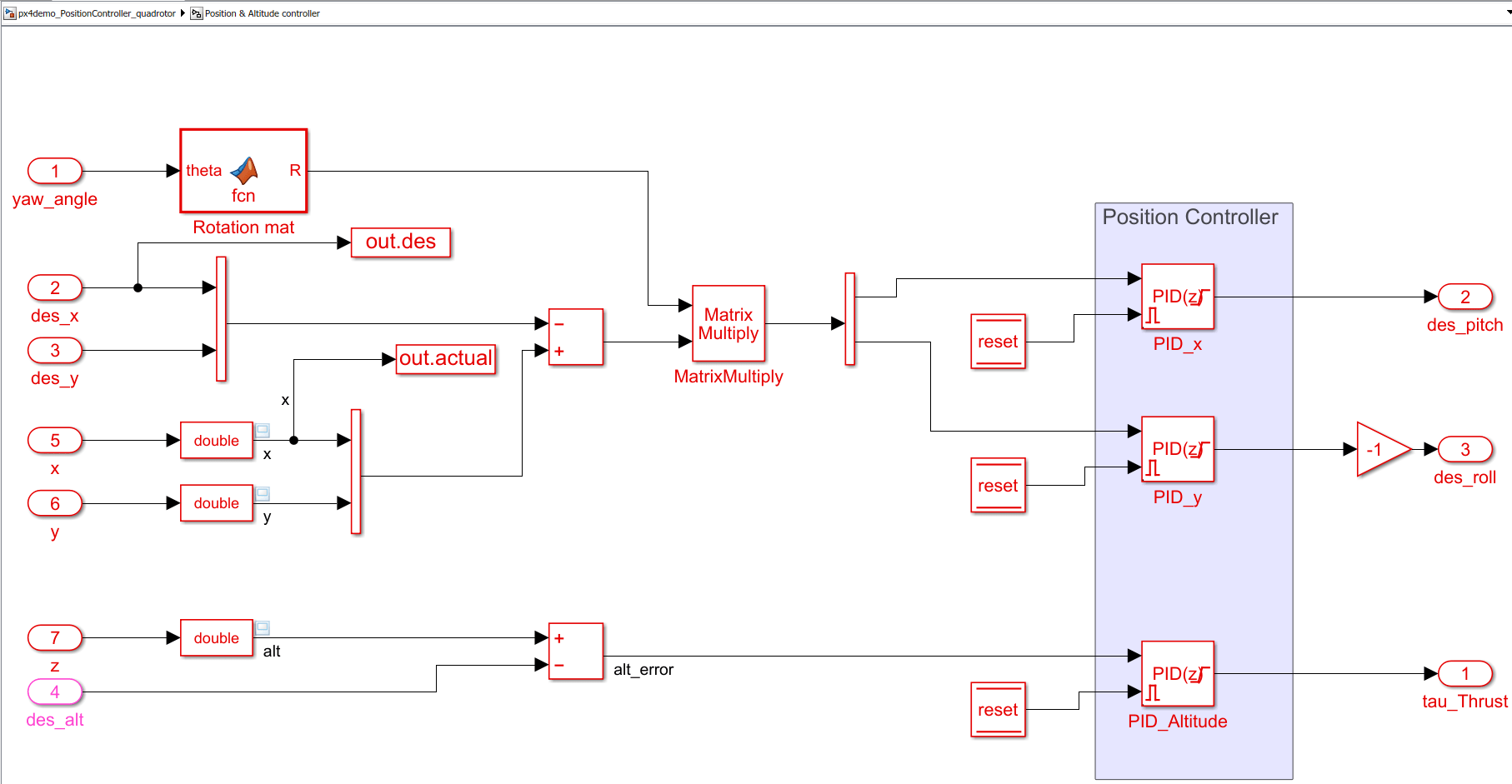
In this example, consider the influence of wind gust on the quadcopter while it is flying. The quadcopter must try to maintain the desired position and altitude. According to the error in position, the pitch and roll commands are generated and the output to the actuator motors are modified.
The Input Sliders in the example model can be used to provide the desired coordinates of the flight of the quadcopter.

The variable des_alt represents an altitude at which the vehicle hovers. The altitude value can be set using the respective slider or directly changing the value of constant des_alt.
The desired position for X and Y can be set by assigning desired values to constants des_x and des_y or using respective sliders.
In the Desired Position, Altitude and Yaw area, you can also provide dynamic inputs (instead of only static inputs) to test the tracking capabilities of the position controller. In this example, the sine wave is used as the dynamic input and can be selected using respective manual switches.

The vehicle's position in the NED reference frame and its rates can be accessed using uORB Read block, which is configured to read the message 'vehicle_local_position'.

Task 2 - Design Position Controller

In the Position & Altitude Control subsystem, three separate PID blocks utilizes the difference between the desired value and the current value (that is read using the uORB read block) to generate the requirement for rotation angles pitch and roll. An output of each PID block is restricted between the predefined maximum and minimum values to limit roll and pitch angles. The limit is set at 40 degrees for this example. The maximum limit of pitch and roll angle is usually inferred from vehicle characteristics, and for a more agile vehicle, it can be higher.

Each PID block utilizes filtered derivatives to eliminate the amplification of any undesired noise signal due to signal differentiation.
The NED reference frame is an inertial reference frame and the direction of the respective axis remains fixed with respect to a starting position on the ground. On the contrary the rotation angles, roll and pitch are measured with respect to a moving reference frame that is attached to vehicle's body. This is because actuators are rigidly mounted with vehicle body. Any non-zero yaw angle changes vehicle heading and orientation of the vehicle in NED reference frame. This results in a phenomenon where, depending on the yaw angle of the vehicle, the same pitch or roll angle causes different translation motion in a plane. Hence, you must account for the non-zero yaw angle while generating pitch and roll commands from the position error. This has been achieved by calculating a 2-D rotation matrix and multiplying position error with the rotation matrix.

Task 3 - Design Attitude Controller and Mix Angular Rate Demands
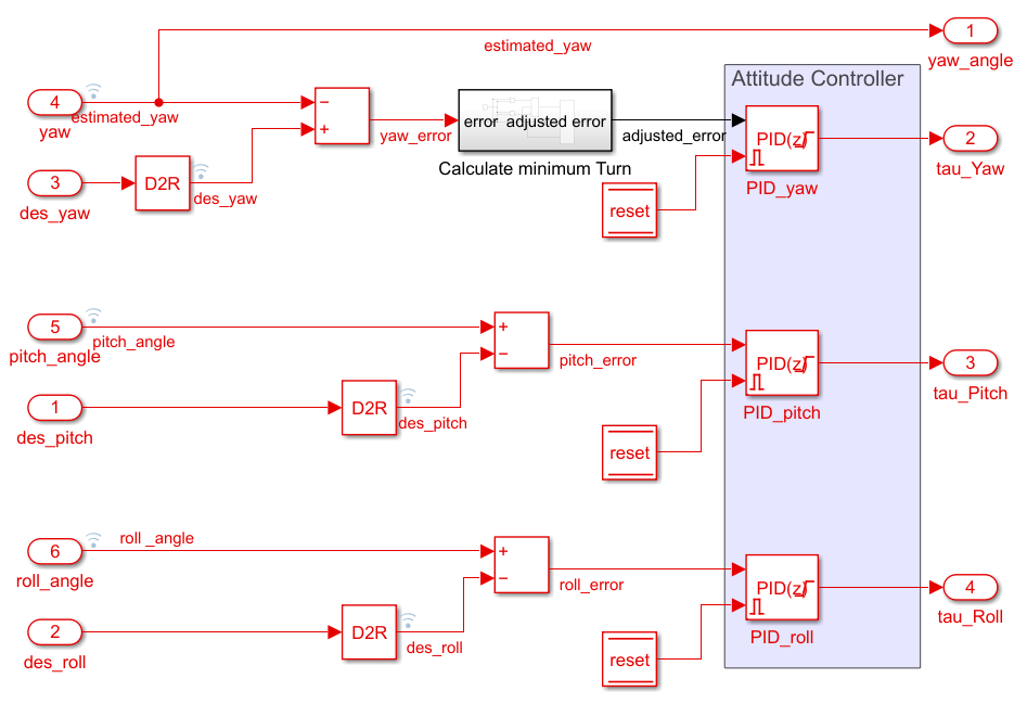
The Attitude Controller acts on the outputs from the Position Controller and modifies actuator output to achieve the desired pitch and roll. The design of the attitude controller and mixing algorithm is similar to the example Attitude Control for X-Configuration Quadcopter Using External Input.
Any non-zero yaw angle changes vehicle heading. So you must account for the non-zero yaw angle while generating pitch and roll commands from the position error.


Task 4 - Tune PID Using Monitor and Tune
For instructions to build the model and perform Monitor and Tune operation with data monitoring, refer to the example Attitude Control for X-Configuration Quadcopter Using External Input.
When you start Monitor and Tune, the jMaVSim simulator is also launched.
In this example, you can use the Monitor and Tune functionality to change the PID values. Each PID gain can be connected to individual sliders and the gain values can be altered using sliders while simulating in external mode. The Tuning Sliders area in the model helps you to achieve this. The effect of any changes in gains can be observed in real-time using various Scope blocks.
The following figure shows one such tuning subsystem. Here, the desired value of the yaw angle is connected to a slider, which can be used to modify the desired yaw angle while simulating the model in external mode. The desired and actual value of yaw angle can be connected to the scope, and the response of the vehicle to any change in desired value can be observed. According to the vehicle response, gains can be adjusted from the respective sliders, and the process of giving an excitation and observing the response can be repeated.

While tuning various PID controllers for the desired response, you may encounter frequent crashes or diverging oscillations in any degree of freedom. The vehicle state can be restored to its initial state using jMAVSim simulator. However, the accumulated integral part of various PID controllers will again destabilize the vehicle even if the vehicle state has been restored to its initial state. This can be avoided by using an external reset for the PID block.
In this example, all PID blocks are configured for external reset and the reset variable is connected to a toggle switch. In the event where a reset of vehicle state is required, the toggle switch can be set to high. This resets all the accumulated integral part and send minimum output to actuators. Once the state is restored using jMAVSim, the toggle switch can be set to low, and this results in a normal controller operation.

To fine-tune the system response and evaluate the controller design, various performance metrics such as Integrated Squared Error (ISE), Integrated Absolute Error (IAE), Integrated Time Squared Error (ITSE), and Maximum Peak overshoot (Mp) can be utilized.
A considerable value of each performance metric reveals a particular flaw in the controller, and hence allows you to take further steps to rectify the flaw and achieve the desired response. For example:
A system with small sustained oscillations around the setpoint has a large IAE.
A system with a slow response to the applied input has a large ISE.
A system with a small steady-state error has a large ITSE.
The applied excitation and response of the system can be logged for a certain time to calculate such performance metrics. The ToWorkspace block of Simulink can be used to log various variables into the MATLAB® workspace. For configuration of logging parameters during the external mode of simulation, refer to Set External Mode Properties for Logging to Workspace.
Once variables are logged, an error can be calculated and normalized using applied input. The normalized error history along with time, can be utilized further to calculate ISE, IAE, ITSE and Mp.
The following figure shows an example of such a process for control system design.

In this example, starting from an origin, a step input of 20m is applied in the x-direction at 15s, and the vehicle response for the total 40s is recorded.
1. Figure A indicates that the controller is not able to correct the overshoot, and hence the response has a large steady-state error.
2. Figure B indicates the improved response due to increment in the proportional gain. Except for the overshoot, all the performance metrics are improved.
3. Figure C indicates improvement in transient response due to increment in the derivative gain. It can be observed from Figure C that, all the performance metrics except the peak overshoot, remains the same as the earlier case. This observation indicates direct correlation between overshoot and derivative gain.
4. Any excessive derivative gain can result in a sluggish response. This phenomenon can be seen in Figure C and Figure D, where increasing the derivative gain further results in a slow system response with comparatively high ISE and IAE.
Limitations of Design with Position Controller

Figure E and Figure F show a vehicle response to a step input for altitude 20m and 50m, respectively.
For a step input of 20m, there is no overshoot in the vehicle response. However, for a step input of 50m, there is a considerable overshoot. Hence, even though this controller can be tuned to give the desired response for a certain type and magnitude of input signals, the same response cannot be achieved for a vast range of operations.
If the initial desired XY position is non-zero, then depending on the desired position, the controller may not be able to handle position and altitude error simultaneously and the vehicle may crash.
For details about the limitation and improvement of the present controller, see Position Tracking for X-Configuration Quadcopter Using Rate Controller.