Implement Component Behavior Using Simscape
A physical subsystem is a Simulink® subsystem with Simscape™ connections. A physical subsystem with Simscape connections uses a physical network approach suited for simulating systems with real physical components and represents a mathematical model.
Using Simscape behaviors for components in System Composer™ improves model simulation and design for systems with physical components. This functionality requires a Simscape license. For more information, see Basic Principles of Modeling Physical Networks (Simscape).
You can simulate the Simscape component implementations in System Composer. Use the Simulation Data Inspector to view and compare simulation results between model designs.
Tip
To learn more about how System Composer concepts apply to systems engineering design, see System Composer Concepts.
To describe component behavior in Simscape for a System Composer architecture model, follow these steps:
Open this model to interact with a System Composer architecture model named Fan with Simscape behavior on a component DC Motor. The steps in this
tutorial will produce this model.
Note
This example uses Simscape blocks. If you do not have a Simscape license, you can open the model but can only make basic changes, such as modifying block parameters.
Architecture Model with Simscape Behavior for a DC Motor
This example shows a DC motor in an architecture model of a fan. The DC motor is modeled using a Simscape behavior within a Simulink subsystem component.
systemcomposer.openModel("Fan");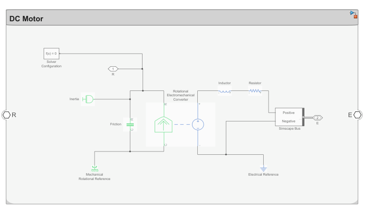
Define Physical Ports on Component
A physical port represents a Simscape physical modeling connector port called a Connection Port (Simscape). Use physical ports to connect components in an architecture model or to enable physical systems in a Simulink subsystem.
Create a new System Composer architecture model. Add a component called DC
Motor to the canvas. To add physical ports to the
component, pause on the boundary of the component until a port outline
appears. Click the port outline and, from the options, select
Physical.

Physical ports can also be used to connect to Simscape blocks.
Note
Components with physical ports cannot be saved as architecture models, model references, software architectures, or Stateflow® chart behaviors. Components with physical ports can only be saved as subsystem references or as subsystem component behaviors.
Specify Physical Interfaces on Ports
You can specify physical interfaces on the physical ports.
A physical interface defines the kind of information that flows through a physical port. The same interface can be assigned to multiple ports. A physical interface is a composite interface equivalent to a Simulink.ConnectionBus object that specifies a number of Simulink.ConnectionElement objects.
Use a physical interface to bundle physical elements to describe a physical model using at least one physical domain.
A physical element describes the decomposition of a physical interface. A physical element is equivalent to a Simulink.ConnectionElement object.
Define the Type of a physical element as a physical domain to enable use of that domain in a physical model.
To open the Interface Editor, navigate to Modeling > Interface Editor.
To add a new physical interface definition, click the list next to the
 icon and select
Physical Interface. Name the
physical interface
icon and select
Physical Interface. Name the
physical interface
ElectricalInterface.To add a physical element to the physical interface, click the
 icon. Physical
interface and physical element names must be valid
MATLAB® variable names. Create the physical elements
icon. Physical
interface and physical element names must be valid
MATLAB® variable names. Create the physical elements
PositiveandNegative.In the Type column, define the Simscape domain to which these physical elements belong. In this case, both belong to
foundation.electrical.electrical.
Select the
Eport on theDC Motorcomponent. Right-click theElectricalInterfacephysical interface on the Interface Editor and click Assign to Selected Port(s).
Note
Newly created ports by default have an <inherit> interface
specification to support unknown interfaces in the early stages of architectural design. If
an interface is specified on another port, as you build your architecture, the
<inherit> specification propagates that interface to other
connected ports. Interface specifications do not automatically propagate through model and
subsystem references.
Create Simulink Subsystem Component
You can create a Simulink subsystem in System Composer to enable direct Simscape integration. For more information, see Create Simulink Behavior Using Subsystem Component.
Select the DC Motor component. Navigate to Modeling > Create Simulink Behavior, or use the right-click menu on the component.

Click OK.

You can convert a subsystem component that is part of the parent System Composer model into a subsystem reference behavior then save and reuse the subsystem as a separate artifact. For more information, see Create Simulink Behavior Using Subsystem Component.
Describe Component Behavior Using Simscape
Double-click the subsystem component to describe component behavior using Simscape. For the DC motor this example is based on, see Evaluating Performance of a DC Motor (Simscape).
The physical interface can be decomposed into physical elements using a Simscape bus. Each physical element represents a conserving connection associated with a domain in Simscape. Simscape buses bundle conserving connections. For more information, see Simscape Bus (Simscape).
Add a Simscape Bus block next to the E
physical port. Double-click the Simscape Bus and select the
connection type Bus: ElectricalInterface. Connect the
E physical port to the Simscape
Bus block. The domain
foundation.electrical.electrical defined under
the Type of the Positive and
Negative physical elements are used for any
connections from these ports.

You can also use owned interfaces defined locally on ports to enable
domain-specific lines on a Simscape behavior model in System Composer. Edit the port interface through the Property Inspector. Navigate to Modeling > Property Inspector. In this case, Simscape Bus blocks are not
needed, and the port can connect directly to the physical connection of the
specified domain. Add an owned physical interface to the physical port
R with Type as a
foundation.mechanical.rotational.rotational
domain. Selecting edit to Open in Interface Editor enters the
Port Interface View in the Interface Editor. For more information, see Define Owned Interfaces Local to Ports.

Using the Library Browser, retrieve the following Simscape blocks and construct the DC Motor model with electrical and rotational mechanical domain-specific connectors. A physical connector can represent a nondirectional conserving connection of a specific physical domain. Connectors can also represent physical signals. Use physical connectors to connect physical components that represent features of a system to simulate mathematically.
For more information, see Domain-Specific Line Styles (Simscape).

Physical modeling uses the network approach and is therefore different from regular Simulink modeling. For more information, see Modeling Best Practices (Simscape) and Troubleshooting Simulation Errors (Simscape).
See Also
createSimulinkBehavior | addPort | addPhysicalInterface | addElement | setInterface | createInterface
Topics
- DC Fast Charging Station for Electric Vehicles with Solar Cogeneration (Simscape Electrical)
- Visualize Mass-Spring-Damper Data in System Composer with Dashboard Block
- Decompose and Reuse Components
- Implement Component Behavior Using Simulink
- Implement Component Behavior Using Stateflow Charts
- Define Port Interfaces Between Components