RS-232 Legacy Drivers
There are components that make up the RS-232 legacy drivers. You can create a model by using these drivers. These drivers perform RS-232 asynchronous communications.
The Simulink® Real-Time™ software provides legacy drivers that support the target computer (main board) serial ports.
These drivers encapsulate the functionality of the device by using the Legacy Serial Port block and the Legacy Serial Port F blocks. For most RS-232 requirements, you can use these RS-232 drivers. For modem requirements, use the Modem Control block and Modem Status block.
Add RS-232 Blocks
When you want to use the serial ports on the target computer for serial I/O, add RS-232 Legacy Serial Port or Legacy Serial Port F subsystem blocks to your Simulink® model.
Before you start, decide what legacy serial ports you want to use. The example has you configure the Legacy Serial Port block. To configure this block, first select serial ports.
Setup Serial Port I/O on Target Computer
The following procedure shows how to use the serial ports on the target computer for I/O with the legacy drivers. It shows a model that uses legacy serial port 1 and legacy serial port 2.
1. Open the Simulink® Real-Time™ block library. You can access the library from the Simulink Library Browser. In the Simulink Editor, on the Real-Time tab, from the Prepare section, click Library Browser. In the left pane, double-click Simulink Real-Time, and then click RS232. To open the library from the MATLAB Command Window, type:
slrealtimelib

2. In the Simulink Real-Time driver block library, double-click the RS232 group block.
3. In the window with blocks for RS-232 legacy drivers, drag an ASCII Encode block to your Simulink model. This block encodes input for the Legacy Serial Port block XMT port.
4. Configure this block.
5. Drag an ASCII Decode block to your Simulink model. This block decodes output from the Legacy Serial Port block RCV port.
6. Configure this block.
7. Double-click the Mainboard group block.
8. Drag two Legacy Serial Port blocks to your Simulink model.
9. Double-click the first Legacy Serial Port block.
10. Configure this block for Legacy Serial Port 1
11. Double-click the second Legacy Serial Port block.
12. Configure this block for Legacy Serial Port 2
13. Add a Pulse Generator block and a target Scope block.
14. Configure the Pulse Generator block so that its Pulse type is Sample based. The dialog box changes to display a Sample time parameter. Enter a Sample time that is slower than the one you set for Receive Setup.
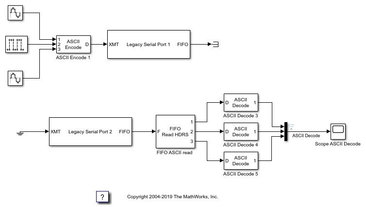
15. From the Simulink Library Browser, select Sinks. Depending on your configuration, drag one or more Terminator blocks to your model. From the Simulink Library Browser, select Sources. Depending on your configuration, drag the Ground block to your model. A pre-constructed example model is available. The slrt_ex_serialbaseboardasciitest model uses two legacy serial ports. To open this model, in the MATLAB Command Window, type:
open_system('slrt_ex_serialbaseboardasciitest')
Your next task is to build and run the real-time application.
Close the Model
bdclose("all");
Building and Running the Real-Time Application
The Simulink Real-Time and Simulink Coder™ software create C code from your Simulink model. You can then use a C compiler to create executable code that runs on the target computer. You must know how to configure your model to create a real-time application. See Build and Download Real-Time Application by Using Run on Target.
After you add the RS-232 blocks for the main board to your Simulink model and configure your model, you can build your real-time application.
In the Simulink Editor, on the Real-Time tab, click Run on Target.
Simulink Real-Time RS-232 Reference
The Simulink Real-Time software supports RS-232 communication by using driver blocks in your Simulink model.
RS-232 FIFO Read Blocks
There are three kinds of FIFO Read blocks: FIFO Read, FIFO Read HDRS, and FIFO Read Binary. To develop your model, use the following guidelines:
Simple data streams — Use the FIFO Read block to read simple data streams. An example of a simple data stream is one that has numbers separated by spaces and ends with a new-line character. The FIFO Read block is a simple block that can easily extract these numbers.
Complicated data streams — Use the FIFO Read HDRS and FIFO Read Binary blocks for more complicated data streams. A more complicated data stream can be one that contains headers, messages of varying lengths, or messages without specific terminators. A message header consists of one or more character identifiers at the beginning of a message that specify what data follows. ASCII messages normally have a variable length and a terminator. Typically, the messages of a particular device use the same predefined terminator. Binary messages are normally of fixed length without a specific terminator.
You can also use the FIFO Read HDRS and FIFO Read Binary blocks to work with devices that can send different messages at different times.
The input to these FIFO read blocks must be of type serialfifoptr,
which is output from F type Send Receive subsystems.
These examples show instances when you can use the FIFO Read block.
For an instrument that sends a character vector like this one:
<number> <number> ... <CR><LF>
use the simple FIFO Read block to read the message. Configure the FIFO Read block Delimiter parameter for a line feed (value of 10). Connect the output to an ASCII Decode block with a format that separates the numbers and feeds them to the output ports.
For an instrument that can send one of several different messages, each beginning with a different fixed character vector, use the FIFO Read HDRS block. For example, a digital multimeter connected through an RS-232 port sends a voltage and amp reading with messages in this format:
volts <number> <CR><LF>
amps <number> <CR><LF>
Configure the FIFO Read HDRS block Header parameter for the
voltsandampsheaders in a cell array:{'volts', 'amps'}. Configure the Terminating string parameter for carriage return (13) and line feed (10):[13 10].Connect the output to multiple ASCII Decode blocks, one for each header and message. For examples of how to use this block in a model, see the
slrt_ex_serialasciitestandslrt_ex_serialasciisplitmodels. To find and open these models, in the MATLAB® Command Window, type:modelfinder('slrealtime')For an instrument that sends a binary message, you could know the length of each full message, including the header. Configure the FIFO Read Binary block Header parameter for the headers of the message in a cell array and the Message Lengths parameter for the message lengths. Example models
slrt_ex_serialbinarytestandslrt_ex_serialbinarysplitshow how to use this block in a model. To find and open these models, in the MATLAB Command Window, type:modelfinder('slrealtime')
RS-232 Signal Data Types
Signals between blocks in composite drivers can be one of several basic data types: 8-bit, 16-bit, and 32-bit. These types are structures.
The 8-bit data types are NULL-terminated character vectors that are represented as
Simulink vectors. The width is the maximum number of characters that can be stored.
In the figure, M is the actual set of stored characters and
N is the maximum number of characters that can be stored. This figure
illustrates 8-bit int NULL-terminated and 8–bit uint
NULL-terminated data types.
The character vector has 11 characters terminated with a NULL byte
(0). The data type cannot contain a NULL byte as part of the real
data.
The 16-bit and 32-bit data types use the first element of the vector as a count of the
valid data. In the figure of a 16-bit data type, C is the count of the
valid data and N is the width of the vector. This figure illustrates
count + 16-bit int and count + 16-bit uint data
types. This arrangement also applies to count + 32-bit int and count +
32-bit uint data types.
The serial blocks interpret each entry in the vector as a single character. The
low-level Send block writes the low-order byte of each entry to the UART. The 16-bit and
32-bit data types allow the embedding of 8-bit data values, including
0. The 8-bit data type is most useful with the ASCII Encode and Decode
blocks. The 16-bit and 32-bit data types are most useful for binary data streams.
RS-232 Zero Length Messages
Usually, you configure a FIFO read block of your model serial I/O to execute faster than the model receives data. Doing so prevents the receive FIFO buffer from overflowing. You must also configure your model to deal with the possibility that a FIFO Read block does not have a message on its output.
Receive FIFOs can have too few characters for a FIFO read operation. A model that receives serial I/O can have a FIFO Read block that executes in this situation. Depending on how you configure the behavior, this condition causes a FIFO Read block to perform one of these operations:
Return the last message it received.
Return a zero-length message.
The Simulink Real-Time library of composite serial drivers has three FIFO Read blocks: FIFO Read HDRS, FIFO Read Binary, and FIFO Read. For the FIFO Read HDRS or FIFO Read Binary blocks, you configure this behavior by using the Output behavior parameter. The FIFO Read block returns either a new message or a zero-length message.
To execute model code only if a new message arrives, check the first element of the returned vector, depending on the character vector data type:
In the 8-bit data type, the returned character vector is NULL-terminated. If the first element is 0, the character vector has zero length and the FIFO read did not detect a new message.
In the 16-bit and 32-bit data types, the first element is the number of characters in the character vector. This value is 0 if the FIFO read did not detect a new message.
If the message has nonzero length, enable a subsystem to process the new character vector. Otherwise, do not process it.
RS-232 Control When You Send a Message
You can use the structure of both serial data types to control when you send a
message. For more information, see RS-232 Signal Data Types. In both cases, a 0
in the first position indicates an empty character vector.
8-bit data types — A value of
0in the first position is the NULL terminator for the character vector.16-bit and 32-bit data types — The first position is the number of characters that follow.
If you connect an empty character vector to the XMT port on one of the send/receive subsystems, no characters are pushed onto the transmit FIFO. You can get this empty character vector by using one of these methods:
To send a specific character vector occasionally, use the Product, Matrix Multiply block to multiply the entire character vector by either
0or1. In this case, the0or1value becomes a transmit enable. To optimize this operation, use a Demux block to extract the first element. Multiply just that element by0or1, then use the Mux block to combine it again.Use a Manual Switch, Multiport Switch, or Switch block. Configure the blocks for two ports to choose between different messages, with one of the choices being a vector of
0values. The Switch block chooses only between vectors of the same width. Because the character vector length does not use the whole vector, you can pad your data to the same width with0values.
See Also
ASCII Encode | ASCII Decode | FIFO Read | FIFO Write | FIFO Read HDRS | FIFO Read Binary | Modem Control | Modem Status | ASCII Decode V2 | Legacy Serial Read | Legacy Serial Setup | Legacy Serial Write | Legacy Serial Port | Legacy Serial Port F
Related Topics
You can also select a web site from the following list:
Americas
- América Latina (Español)
- Canada (English)
- United States (English)
Europe
- Belgium (English)
- Denmark (English)
- Deutschland (Deutsch)
- España (Español)
- Finland (English)
- France (Français)
- Ireland (English)
- Italia (Italiano)
- Luxembourg (English)
- Netherlands (English)
- Norway (English)
- Österreich (Deutsch)
- Portugal (English)
- Sweden (English)
- Switzerland
- United Kingdom (English)