Switch
두 번째 입력의 값에 따라 첫 번째 입력과 세 번째 입력 간 출력 전환
라이브러리:
Simulink /
Commonly Used Blocks
Simulink /
Signal Routing
HDL Coder /
Commonly Used Blocks
HDL Coder /
Signal Routing
설명
Switch 블록은 두 번째 입력의 값에 따라 첫 번째 입력 또는 세 번째 입력을 전달합니다. 첫 번째 입력과 세 번째 입력은 데이터 입력이라고 합니다. 두 번째 입력은 제어 입력이라고 합니다. 첫 번째 입력 전달 조건 파라미터와 임계값 파라미터를 사용하여 블록이 첫 번째 입력을 전달할 조건을 지정합니다.
알려진 출력 데이터형을 첫 번째 입력 포트 및 세 번째 입력 포트로 즉시 역전파하려면 출력 데이터형 파라미터를 상속: 내부 규칙을 통해 상속으로 설정하고 모든 데이터 포트 입력의 데이터형이 동일해야 함 체크박스를 선택하십시오.
팁
역전파 상속: 내부 규칙을 통해 상속의 경우, 모든 데이터 포트 입력의 데이터형이 동일해야 함 파라미터가 선택되어 있어야 합니다. 그렇지 않으면 블록은 출력 데이터형을 첫 번째 출력 포트와 세 번째 출력 포트로 자동으로 역전파하지 않습니다.
데이터 입력에 대한 제한 사항
서로 다른 데이터 입력 크기 허용을 선택하면 두 데이터 입력의 크기가 다를 수 있습니다. 그러나 이 블록은 가변 크기 입력 신호를 지원하지 않습니다. 따라서 시뮬레이션 중에 각 입력의 크기를 변경할 수 없습니다.
Switch 블록에 대한 데이터 입력이 버스라면 두 버스의 요소 이름은 동일해야 합니다. 동일한 요소 이름을 사용하면 블록이 어느 입력 버스를 선택하더라도 출력 버스가 동일한 요소 이름을 갖게 됩니다. 모델이 이 요구 사항을 충족하도록 하려면 Bus 객체를 사용하여 버스를 정의하고 요소 이름 불일치 진단을 오류로 설정하십시오. 자세한 내용은 Model Configuration Parameters: Connectivity Diagnostics 항목을 참조하십시오.
블록 아이콘 모양
블록 아이콘을 사용하면 블록 대화 상자를 열지 않고도 첫 번째 입력 전달 조건 및 임계값을 식별할 수 있습니다.
다양한 블록 방향의 포트 순서에 대한 자세한 내용은 Identify Port Location on Rotated or Flipped Block 항목을 참조하십시오.
부울 제어 입력에 대한 블록 동작
제어 입력이 Boolean 신호인 경우 조건과 임계값의 다음 조합 중 하나를 사용하십시오.
u2 >= 임계값, 여기서 임계값은1과 같음u2 > 임계값, 여기서 임계값은0과 같음u2 ~= 0
그 외의 경우에는 Switch 블록은 임계값을 무시하고 신호 라우팅에 부울 입력을 사용합니다. 제어 입력 1의 경우 블록은 첫 번째 입력을 전달하고 제어 입력 0의 경우 블록은 세 번째 입력을 전달합니다. 이 경우 블록 아이콘은 컴파일 시점 이후에 변경되며 T 및 F를 사용하여 각각 첫 번째 입력 및 세 번째 입력에 레이블이 지정됩니다.
데이터형 지원
제어 입력은 고정소수점 및 열거형을 비롯해 Simulink®에서 지원하는 모든 데이터형이 될 수 있습니다. 제어 입력은 복소수일 수 없습니다. 제어 입력이 열거형인 경우 임계값 파라미터는 동일한 열거형 값이어야 합니다.
데이터 입력은 Simulink에서 지원하는 모든 데이터형이 될 수 있습니다. 데이터 입력 중 하나가 열거형이면 다른 입력도 동일한 열거형이어야 합니다.
출력이 열거형인 경우 두 데이터 입력 모두 출력과 동일한 열거형을 사용해야 합니다.
자세한 내용은 Simulink에서 지원되는 데이터형 항목을 참조하십시오.
예제
부울 제어 포트를 사용하는 Switch 블록 예제
이 예제에서는 제어 포트에 대해 부울 입력을 사용하는 Switch 블록을 보여줍니다.

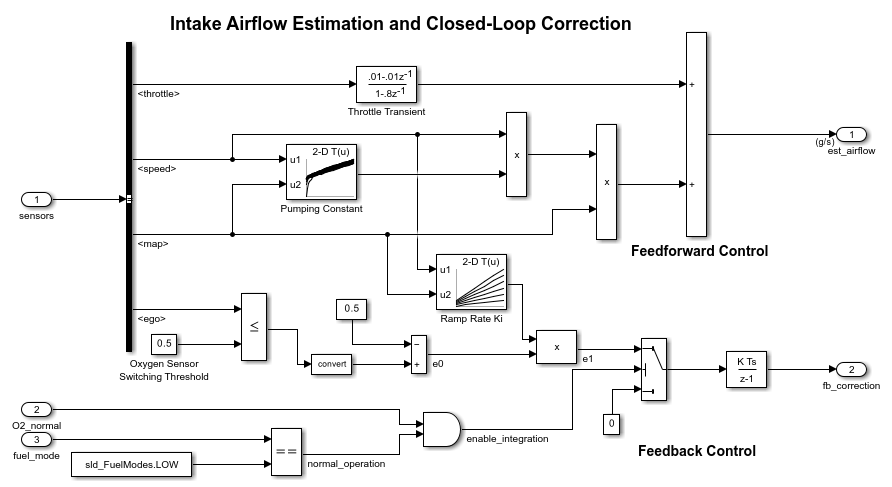
Model Fault-Tolerant Fuel Control System
Combine Stateflow® and Simulink® capabilities to model hybrid systems. This type of modeling is particularly useful for systems that have numerous possible operational modes based on discrete events. Traditional signal flow is handled in Simulink while changes in control configuration are implemented in Stateflow. The model described in this example represents a fuel control system for a gasoline engine. The system is robust in that it detects individual sensor failures, and the control system is dynamically reconfigured for uninterrupted operation.

정확한 영점교차 검출
이 예제에서는 Simulink®에서 영점교차 검출이 어떻게 작동하는지 보여줍니다. Simulink는 영점교차 검출을 사용하여 솔버 시간 스텝을 줄이지 않고도 모델의 급격한 변화나 불연속을 정확하게 시뮬레이션합니다. 자세한 내용은 Zero-Crossing Detection 항목을 참조하십시오.
포트
입력
출력
파라미터
기본
블록이 첫 번째 데이터 입력을 전달할 조건을 선택합니다. 제어 입력이 첫 번째 입력 전달 조건 파라미터에 설정된 조건을 충족하면 블록은 첫 번째 입력을 전달합니다. 그렇지 않으면 블록은 입력 Port_3으로부터 두 번째 데이터 입력 신호를 전달합니다.
-
u2 >= 임계값 제어 입력이 임계값보다 크거나 같은지 확인합니다.
-
u2 > 임계값 제어 입력이 임계값보다 큰지 확인합니다.
-
u2 ~= 0 제어 입력이 0이 아닌지 확인합니다.
참고
Switch 블록은 열거형 데이터형에
u2 ~= 0모드를 지원하지 않습니다.
팁
제어 입력이 부울 신호인 경우 조건과 임계값의 다음 조합 중 하나를 사용하십시오.
u2 >= 임계값(여기서 임계값은 1)u2 > 임계값(여기서 임계값은 0)u2 ~= 0
그렇지 않으면 Switch 블록은 임계값을 무시하고 신호 라우팅에 부울 값을 사용합니다. 값이 1이면 블록은 첫 번째 입력을 전달하고, 값이 0이면 블록은 세 번째 입력을 전달합니다. 또한 이 동작을 설명하는 경고 메시지가 MATLAB® 명령 창에 표시됩니다.
프로그래밍 방식의 사용법
블록 파라미터: Criteria |
| 유형: 문자형 벡터 |
값: 'u2 >= Threshold' | 'u2 > Threshold' | 'u2 ~= 0' |
디폴트 값: 'u2 > Threshold' |
블록이 출력에 전달할 입력을 결정하는 첫 번째 입력 전달 조건에 사용되는 임계값을 할당합니다. 임계값은 출력 최솟값보다 크고 출력 최댓값보다 작아야 합니다.
비 스칼라 임계값을 지정하려면 대괄호를 사용하십시오. 예를 들어, 다음은 유효한 항목입니다.
[1 4 8 12][MyColors.Red, MyColors.Blue]
종속성
첫 번째 입력 전달 조건을 u2 ~= 0으로 설정하면 이 파라미터는 비활성화됩니다.
프로그래밍 방식의 사용법
블록 파라미터: Threshold |
| 유형: 문자형 벡터 |
| 값: 스칼라 |
디폴트 값: '0'
|
영점교차 검출을 활성화하도록 선택합니다. 자세한 내용은 Zero-Crossing Detection 항목을 참조하십시오.
프로그래밍 방식의 사용법
블록 파라미터: ZeroCross |
| 유형: 문자형 벡터 | string형 |
값: 'off' | 'on' |
디폴트 값: 'on' |
신호 특성
데이터형 도우미를 사용하면 데이터 특성을 쉽게 설정할 수 있습니다. 데이터형 도우미를 사용하려면  을 클릭하십시오. 자세한 내용은 Specify Data Types Using Data Type Assistant 항목을 참조하십시오.
모든 데이터 입력은 동일한 데이터형을 사용해야 합니다.
프로그래밍 방식의 사용법
블록 파라미터: InputSameDT |
| 유형: 문자형 벡터 |
값: 'off' | 'on' |
디폴트 값: 'off' |
소프트웨어에서 검사하는 출력 범위의 하한 값입니다.
이 최솟값을 사용하여 다음 작업이 수행됩니다.
일부 블록에 대해 파라미터 범위 검사(Specify Minimum and Maximum Values for Block Parameters 참조).
시뮬레이션 범위 검사(Specify Signal Ranges 및 Enable Simulation Range Checking 참조).
고정소수점 데이터형의 자동 스케일링.
모델에서 생성한 코드 최적화. 이 최적화 작업은 알고리즘의 코드를 제거하고, SIL 또는 외부 모드 같은 일부 시뮬레이션 모드의 결과에 영향을 줄 수 있습니다. 자세한 내용은 Optimize using the specified minimum and maximum values (Embedded Coder) 항목을 참조하십시오.
팁
출력 최솟값은 실제 출력 신호를 포화시키거나 자르지 않습니다. 대신 Saturation 블록을 사용하십시오.
프로그래밍 방식의 사용법
프로그래밍 방식으로 블록 파라미터 값을 설정하려면 set_param 함수를 사용하십시오.
| 파라미터: | OutMin |
| 값: | '[]' (디폴트 값) | scalar in quotes |
소프트웨어에서 검사하는 출력 범위의 상한 값입니다.
이 최댓값을 사용하여 다음 작업이 수행됩니다.
일부 블록에 대해 파라미터 범위 검사(Specify Minimum and Maximum Values for Block Parameters 참조).
시뮬레이션 범위 검사(Specify Signal Ranges 및 Enable Simulation Range Checking 참조).
고정소수점 데이터형의 자동 스케일링.
모델에서 생성한 코드 최적화. 이 최적화 작업은 알고리즘의 코드를 제거하고, SIL 또는 외부 모드 같은 일부 시뮬레이션 모드의 결과에 영향을 줄 수 있습니다. 자세한 내용은 Optimize using the specified minimum and maximum values (Embedded Coder) 항목을 참조하십시오.
팁
출력 최댓값은 실제 출력 신호를 포화시키거나 자르지 않습니다. 대신 Saturation 블록을 사용하십시오.
프로그래밍 방식의 사용법
프로그래밍 방식으로 블록 파라미터 값을 설정하려면 set_param 함수를 사용하십시오.
| 파라미터: | OutMax |
| 값: | '[]' (디폴트 값) | scalar in quotes |
출력 데이터형을 지정합니다.
- 상속: MSB 유지
소프트웨어는 전체 연산 범위를 유지하는 데이터형을 선택한 다음, 출력 정밀도를 임베디드 타깃 하드웨어에 적합한 크기로 줄입니다.
이 규칙으로 인해 오버플로가 생성되는 일은 없습니다.
- 상속: LSB 유지
연산 정밀도를 유지하는 데이터형을 선택합니다. 하지만 해당 유형(full type)이 임베디드 타깃 하드웨어에 적합하지 않은 경우 범위를 줄입니다. 이 규칙으로 인해 오버플로가 생성될 수 있습니다.
임베디드 타깃 설정을 변경할 경우 그러한 내부 규칙을 통해 선택된 데이터형이 변경될 수 있습니다. 항상 코드 효율성과 수치적 정확도를 동시에 최적화할 수 있는 것은 아닙니다. 규칙이 수치적 정확도 또는 성능의 특정 요건에 부합되지 않으면 다음 옵션 중 하나를 사용하십시오.
명시적으로 출력 데이터형을 지정합니다.
상속: 첫 번째 입력과 동일이라는 간단한 옵션을 사용합니다.명시적으로
fixdt(1,32,16)같은 디폴트 데이터형을 지정한 다음, 모델의 데이터형을 제안하는 고정소수점 툴을 사용합니다. 자세한 내용은fxptdlg(Fixed-Point Designer) 항목을 참조하십시오.고유한 상속 규칙을 지정하려면
상속: 역전파를 통해 상속을 사용한 후 Data Type Propagation 블록을 사용합니다. 이 블록의 사용 방법에 대한 예는 Signal Attributes 라이브러리의 Data Type Propagation Examples 블록에서 볼 수 있습니다.
-
상속: 내부 규칙을 통해 상속 다음 규칙을 사용하여 출력 데이터형을 결정합니다.
첫 번째 입력 포트의 데이터형 출력 데이터형 세 번째 입력 포트보다 더 큰 양수 범위를 가짐 첫 번째 입력 포트에서 상속됨 세 번째 입력 포트와 동일한 양수 범위를 가짐 세 번째 입력 포트에서 상속됨 세 번째 입력 포트보다 더 작은 양수 범위를 가짐 부울 값이고 세 번째 입력 포트는 uint8형임uint8형이고 세 번째 입력 포트는 부울 값임부울 값이고 다른 입력 포트는 int8형임부울 값으로 설정됨 uint8형이고 다른 입력 포트는 부울 값임두 입력 포트의 데이터형 출력 데이터형 입력 유형 중 하나는 부울 값이고 다른 하나는 uint8형임세 번째 데이터 포트의 데이터형으로 설정됨 입력 유형 중 하나는 부울 값이고 다른 하나는 int8형임부울 값으로 설정됨 -
상속: 역전파를 통해 상속 출력 블록에서 데이터형을 채택합니다.
-
상속: 첫 번째 입력과 동일하게 상속 첫 번째 데이터 입력 포트의 데이터형을 사용합니다.
-
double 출력 데이터형을
double형으로 지정합니다.-
single 출력 데이터형을
single형으로 지정합니다.-
half 출력 데이터형을
half형으로 지정합니다.-
int8 출력 데이터형을
int8형으로 지정합니다.-
uint8 출력 데이터형을
uint8형으로 지정합니다.-
int16 출력 데이터형을
int16형으로 지정합니다.-
uint16 출력 데이터형을
uint16형으로 지정합니다.-
int32 출력 데이터형을
int32형으로 지정합니다.-
uint32 출력 데이터형을
uint32형으로 지정합니다.-
int64 출력 데이터형을
int64형으로 지정합니다.-
uint64 출력 데이터형을
uint64형으로 지정합니다.-
fixdt(1,16,0) 출력 데이터형을 고정소수점
fixdt(1,16,0)으로 지정합니다.-
fixdt(1,16,2^0,0) 출력 데이터형을 고정소수점
fixdt(1,16,2^0,0)으로 지정합니다.-
Enum: <class name> 열거형 데이터형을 사용합니다(예:
Enum: BasicColors).-
Simulink.ImageType(480,640,3) Computer Vision Toolbox™가 있을 경우
Simulink.ImageType(Computer Vision Toolbox) 객체를 사용합니다.-
string 출력 데이터형을 string형으로 지정합니다.
-
<데이터형 표현식> 데이터형 객체를 사용합니다(예:
Simulink.NumericType).
팁
출력이 열거형인 경우 두 데이터 입력 모두 출력과 동일한 열거형을 사용해야 합니다.
프로그래밍 방식의 사용법
블록 파라미터: OutDataTypeStr |
| 유형: 문자형 벡터 |
값: 'Inherit: Inherit via internal rule | 'Inherit: Inherit via back propagation' | 'Inherit: Same as first input' | 'double' | 'single' | 'half' | 'int8' | 'uint8' | 'int16' | 'uint16', 'int32' | 'uint32' | 'int64' | 'uint64' | 'fixdt(1,16)' | 'fixdt(1,16,0)' | 'fixdt(1,16,2^0,0)' | Enum: <class name> | Simulink.ImageType(480,640,3) | 'string' | '<data type expression>' |
디폴트 값: 'Inherit: Inherit via internal rule' |
블록에 지정한 데이터형이 고정소수점 툴에 의해 재정의되지 않도록 방지하려면 이 파라미터를 선택합니다. 자세한 내용은 Lock the Output Data Type Setting (Fixed-Point Designer) 항목을 참조하십시오.
프로그래밍 방식의 사용법
블록 파라미터: LockScale |
| 유형: 문자형 벡터 |
값: 'off' | 'on' |
디폴트 값: 'off' |
다음 반올림 모드 중 하나를 선택합니다.
올림(Ceiling)양수와 음수를 모두 양의 무한대 방향으로 올림합니다. MATLAB
ceil함수와 동일합니다.수렴(Convergent)숫자를 표현 가능한 가장 가까운 값으로 반올림합니다. 반올림 경계에 놓인 숫자인 경우 가장 가까운 짝수로 반올림합니다. Fixed-Point Designer™
convergent함수와 동일합니다.내림(Floor)양수와 음수를 모두 음의 무한대 방향으로 내림합니다. MATLAB
floor함수와 동일합니다.최근접(Nearest)숫자를 표현 가능한 가장 가까운 값으로 반올림합니다. 반올림 경계에 놓인 숫자인 경우 양의 무한대 방향으로 올림합니다. Fixed-Point Designer
nearest함수와 동일합니다.반올림(Round)숫자를 표현 가능한 가장 가까운 값으로 반올림합니다. 반올림 경계에 놓인 숫자인 경우 양수는 양의 무한대 방향으로 올림하고 음수는 음의 무한대 방향으로 내림합니다. Fixed-Point Designer
round함수와 동일합니다.최대단순(Simplest)가능한 한 가장 효율적인 반올림 코드를 생성하기 위해 내림과 0 방향으로의 올림/내림 중에서 자동으로 선택합니다.
0 방향(Zero)숫자를 0 방향으로 반올림합니다. MATLAB
fix함수와 동일합니다.
프로그래밍 방식의 사용법
블록 파라미터: RndMeth |
| 유형: 문자형 벡터 |
값: 'Ceiling' | 'Convergent' | 'Floor' | 'Nearest' | 'Round' | 'Simplest' | 'Zero' |
디폴트 값: 'Floor' |
참고 항목
자세한 내용은 반올림 모드 (Fixed-Point Designer) 항목을 참조하십시오.
오버플로 시 포화시킬지 아니면 래핑할지를 지정합니다.
on— 오버플로 시 데이터형이 표현할 수 있는 최솟값 또는 최댓값으로 포화됩니다.off— 오버플로 시 데이터형이 표현할 수 있는 적절한 값으로 래핑됩니다.
예를 들어, 부호 있는 8비트 정수 int8이 표현할 수 있는 최댓값은 127입니다. 블록 연산 결과가 이 최댓값보다 크면 8비트 정수 오버플로가 발생합니다.
이 파라미터를 선택하면 블록 출력이 127에서 포화됩니다. 마찬가지로 블록 출력은 최소 출력값 -128에서 포화됩니다.
이 파라미터를 선택 해제하면 오버플로를 일으키는 값이
int8형으로 해석되어 의도치 않은 결과가 발생할 수 있습니다. 예를 들어,int8형으로 표현된 130(2진수 1000 0010)의 블록 결과는 -126입니다.
팁
모델에 오버플로가 발생할 가능성이 있고 생성된 코드에서 포화 보호를 명시적으로 지정하려는 경우 이 파라미터를 선택해 보십시오.
생성된 코드의 효율성을 최적화하려면 이 파라미터를 선택 해제하는 것이 좋습니다. 이 파라미터를 선택 해제하면 블록이 범위를 벗어난 신호를 처리하는 방법을 과도하게 지정하는 일이 방지됩니다. 자세한 내용은 Troubleshoot Signal Range Errors 항목을 참조하십시오.
이 파라미터를 선택하는 경우 출력이나 결과뿐만 아니라 블록의 모든 내부 연산에 포화가 적용됩니다.
일반적으로 코드 생성 프로세스는 오버플로가 발생할 가능성이 없는 경우를 감지할 수 있습니다. 이 경우, 코드 생성기는 포화 코드를 생성하지 않습니다.
프로그래밍 방식의 사용법
프로그래밍 방식으로 블록 파라미터 값을 설정하려면 set_param 함수를 사용하십시오.
| 파라미터: | SaturateOnIntegerOverflow |
| 값: | 'off' (디폴트 값) | 'on' |
서로 다른 크기의 입력 신호를 허용하려면 이 체크박스를 선택하십시오. 블록은 입력 신호 크기를 출력 신호에 전파합니다. 두 데이터 입력이 가변 크기 신호인 경우 신호의 최대 크기는 같거나 다를 수 있습니다.
프로그래밍 방식의 사용법
블록 파라미터: AllowDiffInputSizes
|
| 유형: 문자형 벡터 |
값: 'on' | 'off' |
디폴트 값: 'off'
|
블록 특성
데이터형 |
|
직접 피드스루 |
|
다차원 신호 |
|
가변 크기 신호 |
|
영점교차 검출 |
|