이 번역 페이지는 최신 내용을 담고 있지 않습니다. 최신 내용을 영문으로 보려면 여기를 클릭하십시오.
BLDC
라이브러리:
Motor Control Blockset /
Electrical Systems /
Motors
설명
BLDC 블록은 120도의 전기각 위치 범위에서 일정하게 유지되는 사다리꼴 역기전력을 갖는 3상 브러시리스 DC(BLDC) 모터를 구현합니다. 이 블록은 3상 입력 전압을 사용해 개별 상 전류를 조정하여 모터 토크 또는 속도를 제어할 수 있습니다.
기본적으로, 이 블록은 시뮬레이션 유형 파라미터를 연속으로 설정하여 시뮬레이션 동안 연속 샘플 시간을 사용합니다. 고정 스텝 시뮬레이션에 이 블록을 사용하려면 이 파라미터를 이산으로 설정하십시오. 그런 다음 샘플 시간(초) 파라미터를 지정하십시오.
모터 구조
다음 그림은 단일 극쌍이 있는 모터를 보여줍니다.
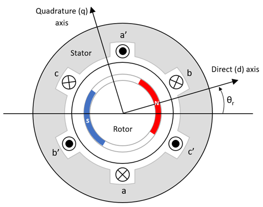
영구 자석으로 인한 모터 자기장은 모터 각도에 따른 플럭스의 사다리꼴 변화율을 생성합니다.
축 규칙에 따라, 모터 각도 θr이 0일 때 a상 자석 플럭스와 영구 자석 플럭스가 정렬됩니다.
3상 정현파 모델 전기 시스템
이 블록은 표준 dq 기준 프레임 대신 다음과 같은 변환 방정식으로 정의되는 d’q’ 기준 프레임을 사용합니다.
이 블록은 BLDC 모터의 dq 기준 프레임과 d’q’ 기준 프레임으로 표현되는 다음과 같은 방정식을 구현합니다. 모터 기준 프레임의 모든 수량은 고정자 A상을 기준으로 합니다.
다음 표에서는 이러한 방정식에 사용되는 변수를 설명합니다.
Lq, Ld | q축 및 d축 인덕턴스(H) |
R | 고정자 권선의 저항(ohm) |
iq', id' | q'축 및 d'축 전류(A) |
vq', vd' | q'축 및 d'축 전압(V) |
ωm | 모터의 기계적 각속도(rad/s) |
ωe | 모터의 전기적 각속도(rad/s) |
P | 극쌍 개수 |
Te | 전자기 토크(Nm) |
Θe | 전기각(rad) |
Va, Vb, Vc | 고정자 A상, B상, C상 전압(V) |
ia, ib, ic | 고정자 A상, B상, C상 전류(A) |
Ea, Eb, Ec | 고정자 A상, B상, C상 역기전력(V/m/s) |
Ψa, Ψb, Ψc | 각 고정자 권선과 쇄교하는 총 플럭스(Wb) |
기계 시스템
모터 각속도는 다음과 같습니다.
방정식에 사용되는 변수는 다음과 같습니다.
J | 모터와 부하의 결합된 관성(kgm^2) |
F | 모터와 부하의 결합된 점성 마찰(N·m/(rad/s)) |
θm | 모터의 기계적 각위치(rad) |
Tm | 모터 샤프트 토크(Nm) |
Te | 전자기 토크(Nm) |
Tf | 모터 샤프트 정적 마찰 토크(Nm) |
ωm | 모터의 기계적 각속도(rad/s) |
진폭 불변 dq 변환
이 블록은 다음 방정식을 사용하여 dq와 3상의 진폭들을 동일하게 하는 진폭 불변 dq 변환을 구현합니다.
방정식에 사용되는 변수는 다음과 같습니다.
Θda | 회전자 a축을 기준으로 한 dq 고정자의 전기각(rad) |
vsq, vsd | 고정자 q축 및 d축 전압(V) |
isq, isd | 고정자 q축 및 d축 전류(A) |
| va, vb, vc | 고정자 전압 a상, b상, c상(V) |
| ia, ib, ic | 고정자 전류 a상, b상, c상(A) |
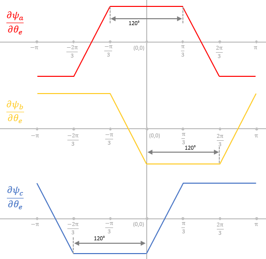
플럭스의 사다리꼴 변화율
영구 자석에 의한 회전자 자기장은 회전자 각도에 따른 플럭스의 사다리꼴 변화율을 생성합니다. 다음 그림은 3상 BLDC 모터의 3상에 대한 플럭스의 변화율을 보여줍니다.
예제

센서 피드백을 사용한 BLDC 모터의 6단계 정류
6단계 정류 기법을 사용하여 3상 BLDC 모터의 회전 속도와 회전 방향을 제어합니다.
포트
입력
출력
파라미터
버전 내역
R2023a에 개발됨