Tracking Scenario Designer
Design tracking scenarios, configure platforms and sensors, and generate synthetic object detections
Description
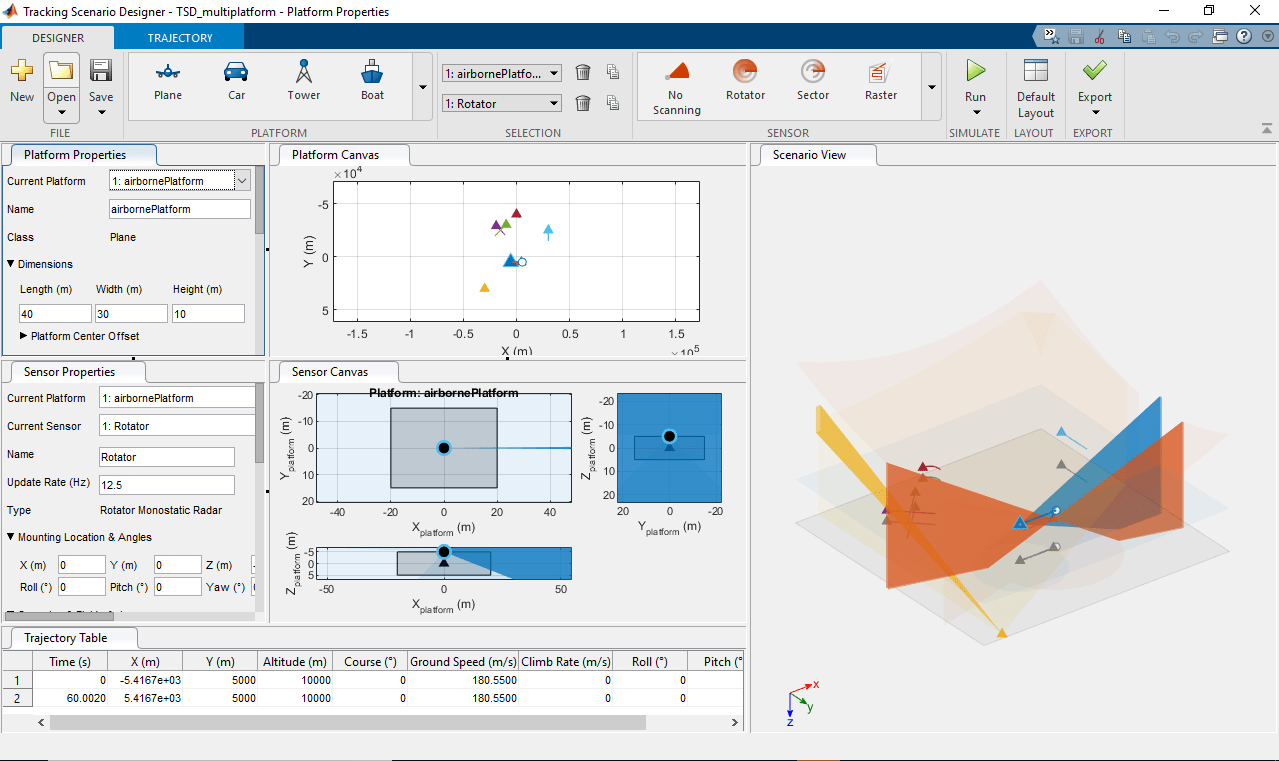
The Tracking Scenario Designer app enables you to design and visualize synthetic tracking scenarios for testing your estimation and tracking systems.
Using the app, you can:
Create platforms (including planes, cars, towers, and boats) using an interactive interface and configure platform properties in the tracking scenario.
Configure 2D or 3D trajectories (including position, orientation, and velocities) of platforms using waypoint trajectories in the tracking scenario.
Create radar sensors mounted on the platform and configure sensor properties.
Simulate the tracking scenario and dynamically visualize the platform trajectories, sensor coverages, and object detections.
Generate MATLAB® code of the scenario and sensors, and then programmatically modify the scenario for application purposes. You can also import the previously saved scenario back into the app for further simulation.
Import a
trackingScenarioobject in the app for visualization and further design of the tracking scenario. See Programmatic Use for the limitations of importing atrackingScenarioobject.
Open the Tracking Scenario Designer App
MATLAB Toolstrip: On the Apps tab, under Radar and Tracking, click the app icon
 .
. MATLAB command prompt: Enter
trackingScenarioDesigner.
Examples
To launch the Tracking Scenario Designer, use the command:
trackingScenarioDesigner
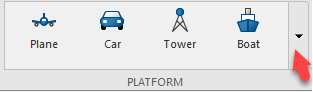
To add a platform in the app, select one platform (tower, for example) form the PLATFORM tab and click the Platform Canvas to place the platform.
![]()
You can change the platform properties through the Platform Properties tab. For example, to set the platform center to the origin, set all initial position coordinates to zero in Initial Pose.
![]()
You can also change the Length, Width, and Height of the platform. By default, the Tower platform's offset in the z direction is half of the platform height, which places the tower center at its bottom. If the offset is zero, then the platform center collocates with the tower's geometric center.
![]()
The center offset is defined as the position vector from the geometric center of a platform to the specified center of the platform.
In the app, you can also specify the uncertainty of the estimated platform pose through the Pose Estimation tab. The value of each parameter in the tab represents the standard deviation of the corresponding quantity. The standard deviation setup is useful for some practical tracking considerations. For example, the accuracy of a sensor mounted on a tower is impacted if the pose of the tower includes errors. In the app, if you set the standard deviations to be nonzero values for a platform with a mounting sensor, you can observe the inaccuracy of the sensor detections introduced by these standard deviations.
![]()
You can also add other platforms in the app. Add a Plane platform on the canvas and set its initial position as [50, -50, 100]. You can see the center of the plane (red) is at its geometric center by default.
![]()
You can change the default setting of any class (and define new classes) using the Platform Gallery Editor, which you can open by clicking the drop-down arrow on the PLATFORM tab.
![]()
You cannot edit the class of a currently used platform. To delete a platform, select the platform from the drop-down list and click the delete (trash can) icon.
![]()
To launch the Tracking Scenario Designer, use the command:
trackingScenarioDesigner
Add a Plane platform on the platform canvas and place the plane at [0, 0, 1000] by specifying its initial position through the Initial Pose tab as:
![]()
Next, add a few waypoints to the platform. Right-click the platform and select Add Waypoints, or select the platform and click Waypoints on the TRAJECTORY toolstrip. Then consecutively click the canvas to add waypoints. To end the action, on the keyboard, click Enter. You can drag the waypoints to change the trajectory. The specified trajectory represents the trajectory of the platform center defined in the Platform Center Offset tab.
![]()
On the TRAJECTORY tab, if the Trajectory Course and the Platform Orientation parameters are set to Auto, the app calculates the trajectory by fitting a smooth curve including all the waypoints and aligning the platform orientation with the trajectory. With Time set to Auto, the app calculates the trajectory duration (Time) based on the default platform speed, which can be specified through the PLATFORM Gallery Editor.
![]()
When Time is selected as Auto, you can also set Jerk Limit to Manual and specify the exact jerk limit (derivative of acceleration) you desire.
![]()
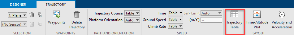
To display the trajectory table below, click Trajectory Table. To display the Time-Altitude plot, click Time-Altitude Plot. To display the velocity and acceleration profile, click Velocity and Acceleration.
![]()
After changing a trajectory parameter selection from Auto to Table, you can edit the corresponding quantity in the Trajectory Table. After you edit the table, observe the change of the trajectory.
You can drag points up and down in altitude in the Time-Altitude plot. After setting Time to Table, you can drag points forward and backward in time.
![]()
To delete a trajectory, select the trajectory and click Delete Trajectory.
![]()
The MAT file TSD_Platforms was previously saved with a tracking scenario session. To launch the application and load the session file, use the command:
trackingScenarioDesigner('TSD_Platforms.mat')
The application opens and loads the scenario. The scenario contains two platforms:
A 60-meter high tower located at the origin of the local NED frame.
A target traveling at a course speed of 750 m/s around the tower.
![]()
Next, mount a sensor on the top of the tower to monitor its surroundings. There are four predefined classes of sensors available in the app.
![]()
You can also click the drop-down arrow to edit the existing classes or add new classes of sensors.
In the app, you select the tower platform, choose a rotator sensor, and place it on the top of the tower. Click the projection button to enable a y-z projection view.
![]()
The sensor is positioned at the bottom of the tower by default. To move the sensor to the top of the tower, change its Mounting Location & Angles.
![]()
Enable detection in the elevation by selecting Report Elevation. Set the sensor's Field of View for Elevation to 15 deg to allow a wide coverage region in elevation. Set the Mechanical scan limits for Elevation to [-15, -5] deg to let the sensor "stare up".
![]()
To simulate the tracking scenario and observe the detection of the target generated by the sensor, click Run. (You can also choose Run Without Detections.)
![]()
You find that the sensor generates only one detection. You can let the sensor scan faster and generate more detections by adjusting its scan rate using two parameters:
Update Rate — Determines the number of field of view slices the sensor steps through per second.
Field of View — Determines the width of each sensor field of view slice or beam.
In the app, increase the Update Rate of the sensor to 200 Hz. With the azimuthal field of view set as 1 deg, the resulting scan rate in the azimuth is 200 deg/s, which is above the default Max scan rate (75 deg/s). Increase Max scan rate to 300 deg/s to allow a high scan rate.
Click Run to simulate the scenario again. The sensor now generates multiple sets of detections.
![]()
You can also export the script of the scenario by clicking Export. Using the exported script, you can modify the scenario programmatically and use the generated scenario to test various tracking algorithms. See Design and Simulate Tracking Scenario with Tracking Scenario Designer example for more details on how to modify the generated scenario.
Related Examples
Parameters
To enable the Platform Properties parameters, add at least one platform to the scenario. Then, select a platform from either the Platform Canvas or the Platform Properties parameter. The parameter values in the Platform Properties tab are based on the platform that you select.
| Parameter | Description |
|---|---|
| Current Platform | Currently selected platform, specified as a list of platforms in the scenario. |
| Name | Name of platform, specified as a string. |
| Class | Platform class, specified as |
You can change the default settings (such as Speed) of the four platform classes and add new platform classes using the Platform Gallery Editor. You can open the editor by clicking the drop-down arrow on the PLATFORM tab and selecting Add/Edit Platform Gallery.
Platform dimensions, specified as Length, Width, and Height in meters.
| Parameter | Description |
|---|---|
| Length (m) | Length of platform, specified as a nonnegative scalar in meters. |
| Width (m) | Width of platform, specified as a nonnegative scalar in meters. |
| Height (m) | Height of platform, specified as a nonnegative scalar in meters. |
You can also specify the Platform Center Offset using the X, Y, and Z offsets. The offset is measured from the geometric center of the platform to the specified center.
| Parameter | Description |
|---|---|
| X (m) | Offset in the x-direction, specified as a scalar in meters. |
| Y (m) | Offset in the y-direction, specified as a scalar in meters. |
| Z (m) | Offset in the z-direction, specified as a scalar in meters. |
Initial position and orientation of platform, specified by three position coordinates X, Y, and Altitude in meters and three rotational angles Roll, Pitch, and Yaw in degrees.
| Parameter | Description |
|---|---|
| X (m) | Initial x coordinate of the platform center in the scenario frame, specified as a scalar in meters. |
| Y (m) | Initial y coordinate of the platform center in the scenario frame, specified as a scalar in meters. |
| Altitude (m) | Initial altitude of the platform center in the scenario frame, specified as a scalar in meters. |
| Roll (°) | Orientation angle of the platform about the x-axis of the scenario frame, specified as a scalar in degrees. |
| Pitch (°) | Orientation angle of the platform about the y-axis of the scenario frame, specified as a scalar in degrees. |
| Yaw (°) | Orientation angle of the platform about the z-axis of the scenario frame, specified as a scalar in degrees. |
Accuracy of the platform pose estimation, specified as standard deviations for three rotational angles : Roll, Pitch, and Yaw, and two translational motion quantities : Position and Velocity.
When the standard deviation value of any motion quantity is specified as nonzero, the platform pose contains errors corresponding to that motion quantity.
| Parameter | Description |
|---|---|
| Roll (°) | Standard deviation of the roll angle of the platform, specified as a scalar in degrees. |
| Pitch (°) | Standard deviation of the pitch angle of the platform, specified as a scalar in degrees. |
| Yaw (°) | Standard deviation of the yaw angle of the platform, specified as a scalar in degrees. |
| Position (m) | Standard deviation of position coordinates of the platform, specified as a scalar in meters. |
| Velocity (m/s) | Standard deviation of velocity coordinates of the platform, specified as a scalar in meters per second. |
Radar cross section information, including RCS pattern information and RCS Viewer specifications. You can specify a constant RCS pattern as a scalar in dBsm, or you can import RCS information through the Import Signature window after selecting the Import RCS tab.
| Parameter | Description |
|---|---|
| Constant RCS Pattern | RCS pattern, specified as a positive constant in dBsm. |
| Import RCS | Import RCS pattern through an Import Signature window. |
You can also specify the RCS Viewer by changing the Elevation Cut in degrees and the Frequency Cut in Hz.
| Parameter | Description |
|---|---|
| Elevation Cut | Elevation cut of RCS viewer, specified as a scalar in degrees. |
| Frequency Cut | Frequency cut of RCS viewer, specified as a scalar in Hz. |
To enable the Sensor Properties parameters, add at least one sensor to the platform. Then, select a sensor from either the Sensor Canvas or the Sensor Properties tab. The parameter values in the Sensor Properties tab are based on the platform and sensor that you select.
| Parameter | Description |
|---|---|
| Current Platform | Current platform on which the sensor is mounted, specified as a list of platforms in the scenario. |
| Current Sensor | Currently selected sensor, specified as a list of sensors in the scenario. |
| Name | Name of sensor, specified as a string. |
| Update Rate | Sensor update rate, specified as a positive scalar in Hz. |
| Type | Sensor type, specified as:
|
Sensor mounting location and angles on the platform, specified by three position coordinates X, Y, and Z in meters and three rotational angles Roll, Pitch, and Yaw in degrees.
| Parameter | Description |
|---|---|
| X (m) | x coordinate of the sensor on the platform frame, specified as a scalar in meters. |
| Y (m) | y coordinate of the sensor on the platform frame, specified as a scalar in meters. |
| Z (m) | z coordinate of the sensor on the platform frame, specified as a scalar in meters. |
| Roll (°) | Orientation angle of the sensor about the x-axis of the platform frame, specified as a scalar in degrees. |
| Pitch (°) | Orientation angle of the sensor about the y-axis of the platform frame, specified as a scalar in degrees. |
| Yaw (°) | Orientation angle of the sensor about the z-axis of the platform frame, specified as a scalar in degrees. |
| Parameter | Description |
|---|---|
| Report Elevation | Enable sensor reporting elevation information, specified as
|
| Scan Mode | Mode of sensor scanning, selected as
|
| Field of View (°) | Field of view of the sensor, specified as two nonnegative scalars representing Azimuth and Elevation in degrees. |
| Mechanical scan limits (°) | Upper and lower limits of mechanical scan, specified as two scalars for Azimuth in degrees. If Report Elevation is enabled, you can specify the scan limits for Elevation in degrees. To enable this parameter, set the Scan
Mode to |
| Electronic scan limits (°) | Upper and lower limits of electronic scan, specified as two scalars for Azimuth in degrees. If Report Elevation is enabled, you can specify the scan limits for Elevation in degrees. To enable this parameter, set the Scan
Mode to |
| Max scan rate (°/s) | Maximum scan rate, specified as a scalar for Azimuth in degrees per second. If Report Elevation is enabled, you can specify the maximum scan rate for Elevation in degrees per second. If the specified scan rate (Update Rate * Field of View) is larger than the Max scan rate, the sensor scan rate is truncated at the Max scan rate. To enable this
parameter, set the Scan Mode to
|
Detection settings of the sensor, specified by using detections probability, false alarm rate, reference range, and reference RCS.
| Parameter | Description |
|---|---|
| Detection Probability | Probability of sensor successfully detecting a target, specified as a scalar in [0,1]. This quantity defines the probability of detecting a target with a radar cross-section larger than the Reference RCS and within the Reference Range of the sensor. |
| False Alarm Rate | Probability of sensor making a false detection in each sensor resolution cell, specified as a scalar in [1e-7,1e-3]. |
| Reference Range (m) | Reference range for the given Detection Probability and the given Reference RCS, specified as a positive scalar in meters. |
| Reference RCS (dBsm) | Reference radar cross-section (RCS) for the given Detection Probability and the given Reference Range, specified as a scalar in dBsm. |
Advanced settings of the sensor are listed in this table.
| Parameter | Description |
|---|---|
| Max Number of Detections | Maximum number of detections reported by the sensor, specified as a positive integer. |
| Report False Alarm | Enable the sensor to model and report false alarms, specified
as |
| Report Range Rate | Enable the radar to measure and report target range rates,
specified as |
| Model Target Occlusion | Enable occlusion of objects from extended objects, specified
as |
| Model Range Ambiguity | Enable range ambiguities, specified as |
| Model Range Rate Ambiguity | Enable range-rate ambiguities, specified as
To enable
this parameter, set Report Range Rate to
|
| Max Unambiguous Range (m) | Maximum unambiguous range, specified as a positive scalar. Maximum unambiguous range defines the maximum range for which the radar can unambiguously resolve the range of a target. |
| Max Unambiguous Radial Speed (m/s) | Maximum unambiguous radial speed, specified as a positive scalar. Radial speed is the magnitude of the target range rate. Maximum unambiguous radial speed defines the radial speed for which the radar can unambiguously resolve the range rate of a target. To enable this parameter, set Report Range
Rate to |
The accuracy and noise setting of the sensor are listed in this table.
| Parameter | Description |
|---|---|
| Azimuth (°) | Azimuth resolution and bias, specified as two nonnegative scalars:
|
| Elevation (°) | Elevation resolution and bias, specified as two nonnegative scalars:
To enable this parameter, turn on Report Elevation. |
| Range (m) | Range resolution and bias, specified as two nonnegative scalars:
|
| Range Rate (m/s) | Range rate resolution and bias, specified as two nonnegative scalars:
|
| Add noise to measurements | Add measurement noise in the detections, specified as
|
To edit the trajectory and control the trajectory generation, use the trajectory settings.
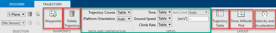
Click Waypoints to add waypoints to a selected platform.
Click Delete Trajectory to delete an existing trajectory.
Click Trajectory Table to display the trajectory table.
Click Time-Altitude Plot to display the time vs altitude plot.
Click Velocity and Acceleration to display the velocity and acceleration profiles. The display has five plots:
Ground Speed — Magnitude of the platform velocity projected on the x-y plane of the scenario frame.
Climb Rate — Projection of the platform velocity in the vertical upward direction in the scenario frame.
Platform X Acceleration — Projection of the platform acceleration on the x-axes of the platform body frame.
Platform Y Acceleration — Projection of the platform acceleration on the y-axes of the platform body frame.
Platform Z Acceleration — Projection of the platform acceleration on the z-axes of the platform body frame.
See the Set Up Trajectories of Platforms in Tracking Scenario Designer for details of these plots.
You can also choose to automatically generate the waypoint trajectory or manually input waypoints by changing the selections of the PATH AND ORIENTATION and the SPEED parameters.
| Parameter | Selection |
|---|---|
| Trajectory Course |
|
| Platform Orientation |
|
| Time |
|
| Ground speed |
|
| Climb Rate |
|
| Jerk Limit |
|
Trajectory information for each waypoint, specified as a table of scalars. When you insert waypoints on the platform canvas, the table is automatically generated. Click Trajectory Table under the Trajectory tab to display the table.
After you change the parameter values in the table, the platform trajectory changes accordingly on the canvas. The table includes these trajectory parameters.
| Parameter | Description |
|---|---|
| Times (s) | Time at which the platform visits the waypoint, specified as a scalar in seconds. |
| X (m) | x coordinate of the waypoint in the scenario navigation frame. |
| Y (m) | y coordinate of the waypoint in the scenario navigation frame. |
| Altitude (m) | Altitude of the platform waypoint in the scenario navigation frame. |
| Course (°) | The direction of motion on the x-y plane, specified as an angle measurement from the x direction. |
| Ground speed (m/s) | Magnitude of the projected velocity on the x-y plane, specified as a scalar in meters. |
| Climb Rate (m/s) | Climb rate of the waypoint, which is the projection of the platform velocity in the z direction. |
| Roll (°) | Orientation angle of the platform about the x-axis of the scenario frame, in degrees, specified as a scalar. |
| Pitch (°) | Orientation angle of the platform about the y-axis of the scenario frame, in degrees, specified as a scalar. |
| Yaw (°) | Orientation angle of the platform about the z-axis of the scenario frame, in degrees, specified as a scalar. |
Programmatic Use
Tips
The app uses the NED frame as the default coordinate frame, in which a platform with positive altitude has negative z coordinate.
You can undo (press Ctrl+Z) and redo (press Ctrl+Y) changes you make on the scenario and sensor canvases. For example, you can use these keyboard shortcuts to delete a recently placed road center or redo the movement of a radar sensor.
You can use the Space bar on the keyboard to reset the Platform Canvas to a view containing all platforms and trajectories.
You can use the Enter and Esc keys on the keyboard to accept and cancel a waypoint, respectively.