Quadcopter Physical Characteristics
This schematic shows these quadcopter physical characteristics:
Axes
Mass and Inertia
Rotors
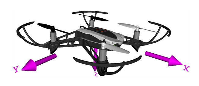
Axes
The quadcopter body axis is centered in the center of gravity.
X-Axis — The X-axis represents the longitudinal axis of the drone, extending from the front to the rear of the drone. Movement along the X-axis involves moving drone forward or backward, and the movement about the X-axis involves rolling motion.
Y-Axis — Movement along the Y-axis involves moving the drone to the left or right, and the movement about the Y-axis involves pitching motion.
Z-Axis — Movement along the Z-axis involves ascending or descending, and the movement about the Z-axis involves yaw motion to change its heading.
These axes are crucial for understanding and controlling the movement and orientation of the drone in three-dimensional space. They are fundamental for drone control, navigation, and stabilization.
Mass and Inertia
Assume that the whole body works as a rigid body of uniform density. The file
vehicleVars contains the values for the inertia and mass.
Rotors
The Parrot® quadcopter minidrone body typically consists of four rotors, often referred to as propellers. These rotors are responsible for generating the lift required for the drone to achieve flight. In most quadcopters, including the Parrot minidrone, the rotors are configured in a cross pattern, with two rotors spinning clockwise and the other two spinning counterclockwise.
This configuration provides stability and control, as the opposing rotation cancels out the rotational torque, ensuring the drone remains level during flight. Additionally, you can independently control the speed of each rotor to enable the drone to change altitude, pitch, roll, and yaw.
The rotor system is a critical component of the design of the drone. The rotor system is key to maneuverability, stability, and overall flight performance.
Rotor 1 rotates positively with respect to the z-axis. This rotor is located parallel to the xy-plane, -45 degrees from the x-axis.
Rotor 2 rotates negatively with respect to the z-axis of the body. This rotor is located parallel to the xy-plane, 45 degrees from the x-axis.
Rotor 3 has the same rotation direction as rotor 1. This rotor is located parallel to the xy-plane, 135 degrees from the x-axis.
Rotor 4 has the same rotation direction as rotor 2. This rotor is located parallel to the xy-plane, -135 degrees from the x-axis.
This example uses the Multirotor block in the Aerospace Blockset™. The block is based on the approach defined by Prouty and adapted to a heavy-lift quadcopter by Pounds, Mahony, and Corke [1].
Command Subsystem
Use one of these options to provide inputs to the quadcopter:
Signal Editor: Use Signal Editor block to provide reference position and orientation reference inputs. Set
VSS_COMMANDto 0 to use Signal Editor to provide inputs.Joystick: Use Pilot Joystick as the input device to provide reference orientation commands. Set
VSS_COMMANDto 1 to use Pilot Joystick to provide inputs.Trajectory Generator: Use the Generate Trajectory live task to generate required polyline trajectory. The variant uses the
generateTraj.mfile in the utilities folder of the project to load any desired map, and generate desired trajectory. SetVSS_COMMANDto 2 to use Trajectory Generator to provide inputs.
To create reference signals for one or more standard predefined trajectories in multivehicle simulations in the Live Task Editor, use Generate Trajectory. For more information, see Generate Trajectories and Reference Signals.
Use the VSS_COMMAND variable in the workspace to make the
appropriate choice. This subsystem generates reference command signal to the control
system.
References
[1] Pounds, P., R. Mahony, and P. Corke. "Modelling and Control of a Large Quadrotor Robot." Control Engineering Practice 18, no. 7 (2010): 691–99. https://doi.org/10.1016/j.conengprac.2010.02.008.
See Also
Rotors | Multirotor | 6DOF (Quaternion) | 6DOF (Euler Angles) | World Magnetic Model | COESA Atmosphere Model | WGS84 Gravity Model | Airport | Apple Hill