Unreal Engine Simulation for Unmanned Aerial Vehicles
UAV Toolbox provides a co-simulation framework that models UAV algorithms in Simulink® and visualizes their performance in a virtual simulation environment. This environment uses the Unreal Engine® from Epic Games®.
Note
Simulating models in the 3D visualization environment requires Simulink 3D Animation™.
Simulink blocks related to the simulation environment can be found in the UAV Toolbox > Simulation 3D block library. These blocks provide the ability to:
Configure prebuilt scenes in the simulation environment.
Place and move UAVs within these scenes.
Set up camera and lidar sensors on the vehicles.
Simulate sensor outputs based on the environment around the UAV.
Obtain ground truth data for semantic segmentation and depth information.
This simulation tool is commonly used to supplement real data when developing, testing, and verifying the performance of UAV flight algorithms. In conjunction with a UAV vehicle model, you can use these blocks to perform realistic closed-loop simulations that encompass the entire UAV flight-control stack, from perception to control.
For more details on the simulation environment, see How Unreal Engine Simulation for UAVs Works.
Unreal Engine Simulation Blocks
To access the UAV Toolbox > Simulation 3D library, at the MATLAB® command prompt, enter uavsim3dlib.
Scenes
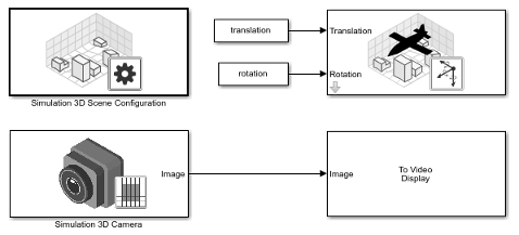
To configure a model to co-simulate with the simulation environment, add a Simulation 3D Scene Configuration block to the model. Using this block, you can choose from a prebuilt scene where you can test and visualize your driving algorithms.
The toolbox includes the US City Block scene which models a city block with intersections, barriers, and traffic lights. For more information on how to simulate with other prebuilt scenes, visit 3D Scenes for Simulation in Unreal Engine Environment
If you have the UAV Toolbox Interface for Unreal Engine Projects support package, then you can modify these scenes or create new ones. For more details, see Customize Unreal Engine Scenes for UAVs.
Vehicles
To define a virtual vehicle in a scene, add a Simulation 3D UAV Vehicle block to your model. Using this block, you can control the movement of the vehicle by supplying the translation and rotation of the UAV at each time step.
You can also specify the color and type of vehicle. The toolbox includes these vehicle types:
Sensors
You can define virtual sensors and attach them at various positions on the vehicles. The toolbox includes these sensor modeling and configuration blocks.
| Block | Description |
|---|---|
| Simulation 3D Camera | Camera model with lens. Includes parameters for image size, focal length, distortion, and skew. |
| Simulation 3D Fisheye Camera | Fisheye camera that can be described using the Scaramuzza camera model. Includes parameters for distortion center, image size, and mapping coefficients. |
| Simulation 3D Lidar | Scanning lidar sensor model. Includes parameters for detection range, resolution, and fields of view. |
| Simulation 3D Ultrasonic Sensor | Ultrasonic sensor model that calculates range measurements based on the distance between the sensor and the closest point on the detected object. |
For more details on choosing a sensor, see Choose a Sensor for Unreal Engine Simulation.
Algorithm Testing and Visualization
UAV Toolbox simulation blocks provide the tools for testing and visualizing path planning, UAV control, and perception algorithms.
Path Planning and Vehicle Control
You can use the Unreal Engine simulation environment to visualize the motion of a vehicle in a
prebuilt scene. This environment provides you with a way to analyze the performance
of path planning and vehicle control algorithms. After designing these algorithms in
Simulink, you can use the uavsim3dlib library to visualize
vehicle motion in one of the prebuilt scenes.
Perception
UAV Toolbox provides several blocks for detailed camera and lidar sensor modeling. By mounting these sensors on UAVs within the virtual environment, you can generate synthetic sensor data or sensor detections to test the performance of your sensor models against perception algorithms.
Closed-Loop Systems
After you design and test a perception system within the simulation environment, you can then use it to drive a control system that actually steers a vehicle. In this case, rather than manually set up a trajectory, the UAV uses the perception system to fly itself. By combining perception and control into a closed-loop system in the 3D simulation environment, you can develop and test more complex algorithms, such as automated delivery.