Main Content

Simulation 3D Fisheye Camera

Fisheye camera sensor model in 3D simulation environment

Since R2019b

  • Simulation 3D Fisheye Camera block

Libraries:
UAV Toolbox / Simulation 3D
Automated Driving Toolbox / Simulation 3D
Simulink 3D Animation / Simulation 3D / Sensors

Description

Note

Simulating models with the Simulation 3D Fisheye Camera block requires Simulink® 3D Animation™ and Computer Vision Toolbox™.

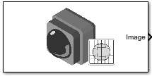
The Simulation 3D Fisheye Camera block provides an interface to a camera with a fisheye lens in a 3D simulation environment. This environment is rendered using the Unreal Engine® from Epic Games®. The sensor is based on the fisheye camera model proposed by Scaramuzza [1]. This model supports a field of view of up to 195 degrees. The block outputs an image with the specified camera distortion and size. You can also output the location and orientation of the camera in the world coordinate system of the scene.

If you set Sample time to -1, the block uses the sample time specified in the Simulation 3D Scene Configuration block. To use this sensor, you must include a Simulation 3D Scene Configuration block in your model.

Tip

The Simulation 3D Scene Configuration block must execute before the Simulation 3D Fisheye Camera block. That way, the Unreal Engine 3D visualization environment prepares the data before the Simulation 3D Fisheye Camera block receives it. To check the block execution order, right-click the blocks and select Properties. On the General tab, confirm these Priority settings:

  • Simulation 3D Scene Configuration0

  • Simulation 3D Fisheye Camera1

For more information about execution order, see How Unreal Engine Simulation for Automated Driving Works (Automated Driving Toolbox).

Ports

Input

expand all

Relative translation of the sensor from its mounting point on the vehicle, in meters, specified as a real-valued 1-by-3 vector of the form [X Y Z].

Dependencies

To enable this port, select the Input parameter next to the Relative translation [X, Y, Z] (m) parameter. When you select Input, the Relative translation [X, Y, Z] (m) parameter specifies the initial relative translation and the Rel Translation port specifies the relative translation during simulation. For more details, see Sensor Position Transformation.

Data Types: single | double | int8 | int16 | int32 | int64 | uint8 | uint16 | uint32 | uint64

Relative rotation of the sensor from its mounting point on the vehicle, in degrees, specified as a real-valued 1-by-3 vector of the form [Roll Pitch Yaw].

Dependencies

To enable this port, select the Input parameter next to the Relative rotation [Roll, Pitch, Yaw] (deg) parameter. When you select Input, the Relative translation [Roll, Pitch, Yaw] (deg) parameter specifies the initial relative rotation and the Rel Rotation port specifies the relative rotation during simulation. For more details, see Sensor Position Transformation.

Data Types: single | double | int8 | int16 | int32 | int64 | uint8 | uint16 | uint32 | uint64

Output

expand all

3D output camera image, returned as an m-by-n-by-3 array of RGB triplet values. m is the vertical resolution of the image, and n is the horizontal resolution of the image.

Data Types: int8 | uint8

Sensor location along the X-axis, Y-axis, and Z-axis of the scene. The Translation values are in the world coordinates of the scene. In this coordinate system, the Z-axis points up from the ground. Units are in meters.

Dependencies

To enable this port, on the Ground Truth tab, select Output location (m) and orientation (rad).

Data Types: double

Roll, pitch, and yaw sensor orientation about the X-axis, Y-axis, and Z-axis of the scene. The Rotation values are in the world coordinates of the scene. These values are positive in the clockwise direction when looking in the positive directions of these axes. Units are in radians.

Dependencies

To enable this port, on the Ground Truth tab, select Output location (m) and orientation (rad).

Data Types: double

Parameters

expand all

Mounting

Specify the unique identifier of the sensor. In a multisensor system, the sensor identifier enables you to distinguish between sensors. When you add a new sensor block to your model, the Sensor identifier of that block is N + 1, where N is the highest Sensor identifier value among the existing sensor blocks in the model.

Example: 2

Name of the parent to which the sensor is mounted, specified as Scene Origin or as the name of a vehicle in your model. The vehicle names that you can select correspond to the Name parameters of the simulation 3D vehicle blocks in your model. If you select Scene Origin, the block places a sensor at the scene origin.

Example: SimulinkVehicle1

Sensor mounting location.

  • When Parent name is Scene Origin, the block mounts the sensor to the origin of the scene. You can set the Mounting location to Origin only. During simulation, the sensor remains stationary.

  • When Parent name is the name of a vehicle, the block mounts the sensor to one of the predefined mounting locations described in the table. During simulation, the sensor travels with the vehicle.

Vehicle Mounting LocationDescriptionOrientation Relative to Vehicle Origin [Roll, Pitch, Yaw] (deg)
Origin

Forward-facing sensor mounted to the Vehicle origin, which is on the ground, at the geometric center of the Vehicle (see Body (Non-Inertial) Coordinate System)

Vehicle with sensor mounted at origin

[0, 0, 0]

Roll, pitch, and yaw are clockwise-positive when looking in the positive direction of the X-axis, Y-axis, and Z-axis, respectively. When looking at a vehicle from above, the yaw angle (the orientation angle) is counterclockwise-positive because you are looking in the negative direction of the axis.

The (X, Y, Z) mounting location of the sensor relative to the vehicle depends on the vehicle type. To specify the vehicle type, use the Type parameter of the Simulation 3D UAV Vehicle block to which you are mounting. To obtain the (X, Y, Z) mounting locations for a vehicle type, see the reference page for that vehicle.

Select this parameter to specify an offset from the mounting location by using the Relative translation [X, Y, Z] (m) and Relative rotation [Roll, Pitch, Yaw] (deg) parameters.

Translation offset relative to the mounting location of the sensor, specified as a real-valued 1-by-3 vector of the form [X, Y, Z]. Units are in meters.

If you mount the sensor to a vehicle by setting Parent name to the name of that vehicle, then X, Y, and Z are in the vehicle coordinate system, where:

  • The X-axis points forward from the vehicle.

  • The Y-axis points to the left of the vehicle, as viewed when looking in the forward direction of the vehicle.

  • The Z-axis points up.

The origin is the mounting location specified in the Mounting location parameter. This origin is different from the vehicle origin, which is the geometric center of the vehicle.

If you mount the sensor to the scene origin by setting Parent name to Scene Origin, then X, Y, and Z are in the world coordinates of the scene.

For more details about the vehicle and world coordinate systems, see Coordinate Systems for Unreal Engine Simulation in UAV Toolbox.

Example: [0,0,0.01]

Adjust Relative Translation During Simulation

To adjust the relative translation of the sensor during simulation, enable the Rel Translation input port by selecting the Input parameter next to the Relative translation [X, Y, Z] (m) parameter. When you enable the Rel Translation port, the Relative translation [X, Y, Z] (m) parameter specifies the initial relative translation of the sensor and the Rel Translation port specifies the relative translation of the sensor during simulation. For more details about the relative translation and rotation of this sensor, see Sensor Position Transformation.

Dependencies

To enable this parameter, select Specify offset.

Rotational offset relative to the mounting location of the sensor, specified as a real-valued 1-by-3 vector of the form [Roll, Pitch, Yaw]. Roll, pitch, and yaw are the angles of rotation about the X-, Y-, and Z-axes, respectively. Units are in degrees.

If you mount the sensor to a vehicle by setting Parent name to the name of that vehicle, then X, Y, and Z are in the vehicle coordinate system, where:

  • The X-axis points forward from the vehicle.

  • The Y-axis points to the left of the vehicle, as viewed when looking in the forward direction of the vehicle.

  • The Z-axis points up.

  • Roll, pitch, and yaw are clockwise-positive when looking in the forward direction of the X-axis, Y-axis, and Z-axis, respectively. If you view a scene from a 2D top-down perspective, then the yaw angle (also called the orientation angle) is counterclockwise-positive because you are viewing the scene in the negative direction of the Z-axis.

The origin is the mounting location specified in the Mounting location parameter. This origin is different from the vehicle origin, which is the geometric center of the vehicle.

If you mount the sensor to the scene origin by setting Parent name to Scene Origin, then X, Y, and Z are in the world coordinates of the scene.

For more details about the vehicle and world coordinate systems, see Coordinate Systems for Unreal Engine Simulation in UAV Toolbox.

Example: [0,0,10]

Adjust Relative Rotation During Simulation

To adjust the relative rotation of the sensor during simulation, enable the Rel Rotation input port by selecting the Input parameter next to the Relative rotation [Roll, Pitch, Yaw] (deg) parameter. When you enable the Rel Rotation port, the Relative rotation [Roll, Pitch, Yaw] (deg) parameter specifies the initial relative rotation of the sensor and the Rel Rotation port specifies the relative rotation of the sensor during simulation. For more details about the relative translation and rotation of this sensor, see Sensor Position Transformation.

Dependencies

To enable this parameter, select Specify offset.

Sample time of the block, in seconds, specified as a positive scalar. The 3D simulation environment frame rate is the inverse of the sample time.

If you set the sample time to -1, the block inherits its sample time from the Simulation 3D Scene Configuration block.

Parameters

These intrinsic camera parameters are equivalent to the properties of a fisheyeIntrinsics (Computer Vision Toolbox) object. To obtain the intrinsic parameters for your camera, use the Camera Calibrator app.

For details about the fisheye camera calibration process, see Using the Single Camera Calibrator App (Computer Vision Toolbox) and Fisheye Calibration Basics (Computer Vision Toolbox).

Center of distortion, specified as real-valued 2-element vector. Units are in pixels.

Image size produced by the camera, specified as a real-valued 1-by-2 vector of positive integers of the form [mrows,ncols]. Units are in pixels.

Polynomial coefficients for the projection function described by Scaramuzza's Taylor model [1], specified as a real-valued 1-by-4 vector of the form [a0 a2 a3 a4].

Example: [320, -0.001, 0, 0]

Transforms a point from the sensor plane to a pixel in the camera image plane. The misalignment occurs during the digitization process when the lens is not parallel to sensor.

Example: [0, 1; 0, 1]

Ground Truth

Select this parameter to output the translation and rotation of the sensor at the Translation and Rotation ports, respectively.

Tips

  • To visualize the camera images that are output by the Image port, use a Video Viewer (Computer Vision Toolbox) or To Video Display (Computer Vision Toolbox) block.

  • Because the Unreal Engine can take a long time to start up between simulations, consider logging the signals that the sensors output. You can then use this data to develop perception algorithms in MATLAB®. See Mark Signals for Logging (Simulink).

Algorithms

expand all

References

[1] Scaramuzza, D., A. Martinelli, and R. Siegwart. "A Toolbox for Easy Calibrating Omindirectional Cameras." Proceedings to IEEE International Conference on Intelligent Robots and Systems (IROS 2006). Beijing, China, October 7–15, 2006.

Version History

Introduced in R2019b

expand all