Run PX4 Autopilot in Hardware-in-the-Loop (HITL) Simulation with UAV Dynamics in Simulink
This example shows how to verify a controller design by deploying on Pixhawk® hardware board in Hardware-in-the-Loop (HITL) mode. Hardware-in-the-Loop (HITL or HIL) is a simulation mode in which normal PX4 firmware is run on real flight controller hardware. This approach lets you test most of the actual flight code on the real autopilot hardware, while the UAV dynamics in Simulink®. To understand the physical connections required to set up the Pixhawk and Simulink for HITL Simulation, go through the PX4 Hardware-in-the-Loop System Architecture.
The UAV Toolbox Support Package for PX4 Autopilots lets you design a flight controller algorithm to follow the mission set in the QGroundControl (QGC). You can design the UAV dynamics in Simulink, simulate sensor values, and communicate with the autopilot in HITL mode.
The example demonstrates two ways to run HITL simulation with a Pixhawk autopilot:
Normal mode, where the controller runs independently on the hardware
Monitor and Tune mode, where you tune and observe the controller in real time from Simulink
Choose HITL Simulation Approach
Select the execution method that best matches your workflow requirements.
Normal Mode
Use Normal mode when you want to validate controller behavior and mission execution with minimal setup and without live interaction from Simulink.
Key Characteristics
The controller is deployed on PX4 autopilot using Embedded Coder® generated code.
UAV dynamics and sensor simulation run on the host computer in Simulink.
Communication between Simulink and the autopilot is limited to MAVLink® data exchange.
Controller parameters cannot be tuned during execution.
Signal logging requires manual configuration.
When to use:
Functional verification
Mission testing
Monitor and Tune Mode
Use monitor and tune mode when you need live access to controller parameters and signals during execution.
Key Characteristics:
The controller is deployed to the PX4 autopilot using Embedded Coder generated code.
Simulink maintains a live connection to the running controller.
You can tune parameters and log signals in real time.
Two MATLAB® sessions are required, typically one per Simulink model.
Setup is more complex due to additional communication paths.
When to use:
Controller tuning
Performance optimization
Detailed signal inspection
Required Hardware
To run this example, you need:
Pixhawk Series flight controller (Pixhawk 6x recommended)
Micro USB (Type-B) cable
Micro-SD card
Serial-to-USB FTDI converter
Mini USB cable for FTDI
Pixhawk serial port connectors
Configure Software and Hardware for HITL
Software Setup
1. Install the UAV Toolbox Support Package for PX4 Autopilots in Windows®. For details, see Install UAV Toolbox Support Package for PX4 Autopilots in Windows. Install Python®, WSL2 and download PX4 source code in WSL2 as described in Additional Information for Hardware Setup.
2. Install QGroundControl version 4.3.0.
Hardware Setup
1. Configure the Pixhawk board for HITL mode using QGroundControl. See, Setting Up PX4 Autopilot in Hardware-in-the-Loop (HITL) Mode from QGroundControl.
2. Set up the PX4 firmware for HITL simulation and specify:
PX4 Autopilot board: any Pixhawk series board. This example uses Pixhawk 6x
Build Target: corresponding build target having _multicopter keyword from drop down list. This example uses
px4_fmu-v6x_multicopter.
See, Set Up PX4 Firmware for Hardware-in-the-Loop (HITL) Simulation.
Load the Project
Open the example project by executing this command at the MATLAB command prompt:
openExample('px4/PX4HITLSimulationSimulinkPlantExample')The project contains two Simulink models:
Controller model- Deployed to the PX4 autopilot and implements navigation, estimation, and control logic.
UAV Dynamics model-Simulates vehicle dynamics, sensors, and MAVLink communication with the autopilot.
Controller Model
This example uses PX4demo_HITLSimulinkPlant.prj project which includes two Simulink models: the controller model (Quadcopter_ControllerWithNavigation.slx) and the UAV dynamics model (UAV_Dynamics_Autopilot_Communication.slx).
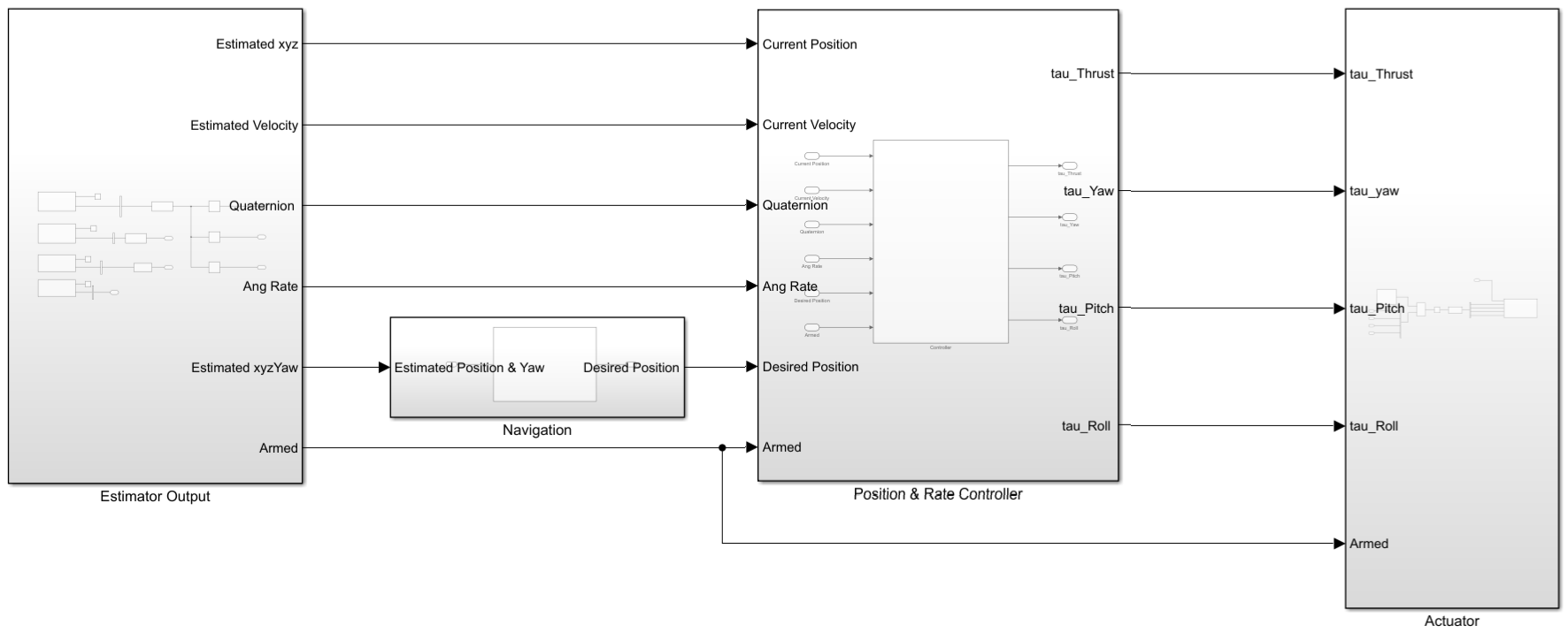
The controller model (Quadcopter_ControllerWithNavigation.slx) represents a typical PX4 compatible flight controller architecture. It includes subsystems for:
Estimator Output - Outputs the estimated position, velocity, angular rate, and arm status by using PX4 uORB Read block. This block creates a nonvirtual bus for the specified uORB topic and reads messages such as VehicleLocalPosition, VehicleAttitude, VehicleOdometry, and ActuatorArmed topics.
Navigation - Uses the PX4 Read Position Setpoint block to read waypoints from QGC. It outputs the coordinates for current destination waypoint, next desired waypoint and the previous waypoint. The Guidance system provides the Desired Position (
Desired_Pose).
Position & Rate Controller - Takes Current Position, Current Velocity, Quaternion, Angular rate, Desired Position and Arm status as inputs from the Estimator output and Navigation subsystems. It uses discrete PID(z) and P(z) controllers in different configurations to obtain the desired
tau_Thrust,tau_Yaw,tau_Pitch, andtau_Rollas inputs for the Actuator subsystem.
Actuator - The Actuator subsystem uses Actuator Write block to set values for the motors.
UAV Dynamics Model
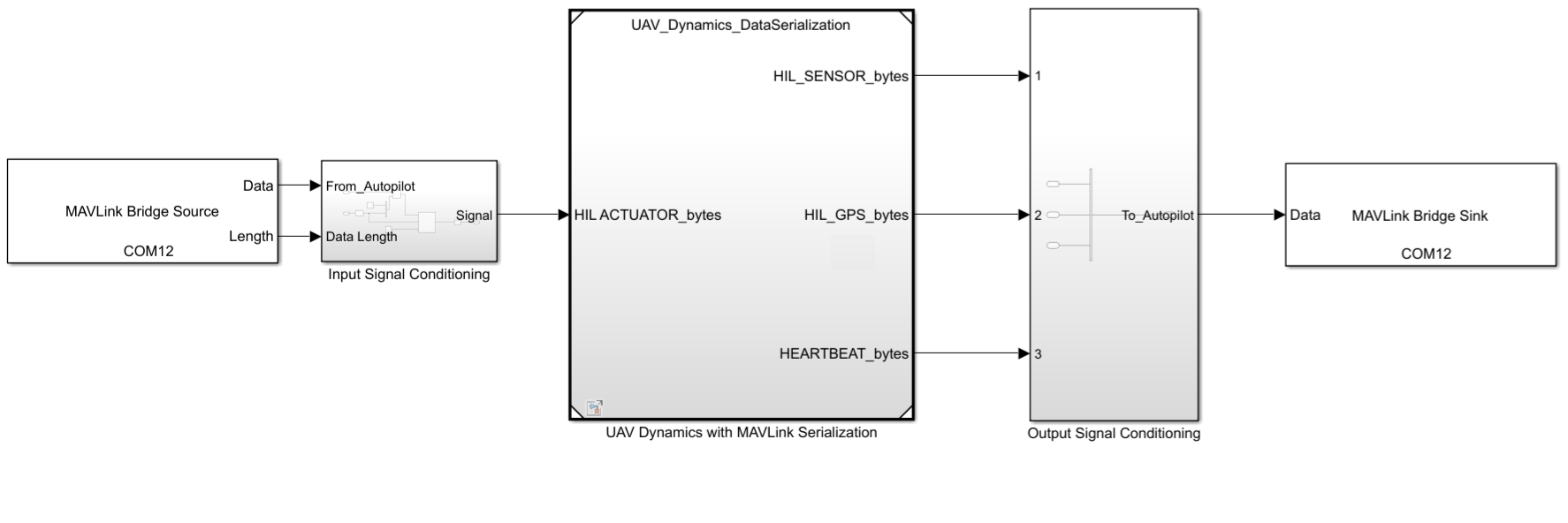
The UAV_Dynamics_Autopilot_Communication.slx Simulink model consists of the following subsystems:
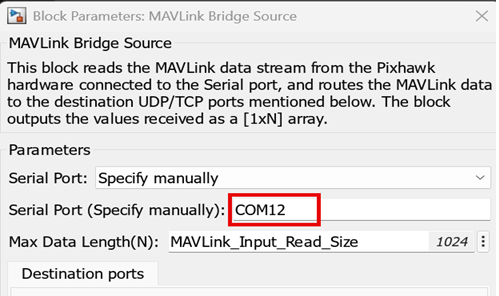
MAVLink Bridge Source - Reads the MAVLink data stream from the Pixhawk hardware connected to the Serial port and routes the MAVLink data to the destination UDP/TCP ports.
Input Signal Conditioning - Conditions the signal from the autopilot based on the data length and reshapes it into the input to the UAV Dynamics with the MAVLink Serialization subsystem.
UAV Dynamics with MAVLink Serialization - Accepts MAVLink data stream and sends control commands to the actuator as PWM inputs. The UAV Dynamics subsystem contains a Quadcopter Model, IMU Simulation, Baro Simulation and GNSS/GPS Simulation subsystems which provide the required data such as
Acc,Gyro,Mag,Pressure,Velocity,GndSpeed,Course. This data helps to construct the MAVLink messages for the Autopilot and they areHIL_SENSOR_bytes,HIL_GPS_bytes. These two messages contains the simulated sensor data to be sent to autopilot. The heartbeat message is sent to identify that the data comes from Simulink.
Output Signal Conditioning -Conditions the signal as a virtual vector and sends the data to the MAVLink Bridge Sink.
MAVLink Bridge Sink - Reads the MAVLink data from the source UDP/TCP ports, merges it with input data, and writes to Pixhawk hardware connected to Serial port.
Deploy Controller over Normal Mode
In Normal Mode, you deploy the controller model to the autopilot without monitor and tune.
Configure Pixhawk Autopilot for HITL Simulation
The diagram illustrates the HITL setup and the communication among various modules.

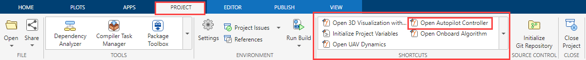
1.Connect the Pixhawk board to the host computer using a USB cable. In the project Shortcuts, click Open Autopilot Controller.The Quadcopter_ControllerWithNavigation model is pre configured for HITL Simulation. If you are using a different model, configure your model for deployment as described in Configure Simulink Model for Deployment in Hardware-in-the-Loop (HITL) Simulation.
2. In the Hardware tab, in the Mode section, click Run on board.
3. Generate code for the controller model and deploy the generated code to the Pixhawk board. To do so, in the Deploy section, click Build, Deploy & Start.

The controller code is deployed to the Pixhawk hardware. Open QGroundControl and establish connection with PX4 autopilot.
Note: If you are using Ubuntu®, to open QGC, open a terminal, go to the location where QGC is downloaded, and run the following command:
./QGroundControl.AppImage
Run UAV Dynamics and Fly Mission
1. In the project shortcuts, click Open UAV Dynamics.
2. Set the correct COM ports in the MAVLink bridge source and MAVLink bridge sink blocks. You can check the device manager on the host computer to find the COM port being used by the Pixhawk hardware.
3. UAV dynamics in Simulink communicates serially with the Pixhawk hardware. To do this, on the Simulation tab, click Run.
4. Configure and assign actuators in QGC. See, Configure Motors and Servos for HITL.

5. In QGroundControl:
Create a mission in Plan view
Upload the mission
Switch to Fly view and start the mission

The UAV follows the mission using HITL simulation.
Deploy Controller for Monitor and Tune
This workflow enables real-time monitoring and tuning of the controller. This method uses two separate MATLAB sessions, each running a different Simulink model. The method lets you monitor and tune the PX4 Autopilot simulation in real time, so you can adjust the algorithm and log signals directly in Simulink using Simulation Data Inspector (SDI). You can inspect and compare data from multiple simulations to validate model designs using Simulation Data Inspector. For more information about monitor and tune process, see Monitor and Tune the Model Running on PX4 Autopilots.
To enable monitor and tune, you need two serial ports, one for MAVLink data and one for a serial-to-USB FTDI converter. In this example, the Pixhawk 6x uses the GPS2 port (dev/ttyS7) to communicate with Simulink on the host computer. For more information about the hardware connection, see Running Monitor & Tune Simulation over FTDI with Pixhawk 6x.
Configure Pixhawk Autopilot for HITL Simulation
The diagram illustrates the HITL setup and the physical communication between various modules. In contrast to normal mode operation, the flight controller communicates to the Pixhawk board GPS2 serial port over FTDI for monitor and tune simulation.

1. Connect your Pixhawk board to the host computer using the USB cable.
2. Connect the Rx & Tx of GPS2 port to the Tx and Rx of the FTDI (Serial to USB Converter) device which is connected to host computer over another USB port.
3. Determine the COM Port for the FTDI device on host computer. To find the COM port used by the Pixhawk hardware, check the Device manager on the host computer.
4. Disable MAVLink on TELEM1, TELEM2, or TELEM3 port of the Pixhawk hardware. Check values of the parameters MAV_0_CONFIG and MAV_1_CONFIG to confirm in QGC.

Open Two MATLAB Sessions
1. Open controller in first MATLAB instance:
In the first MATLAB instance, open the example project.
In the Project tab, in the Shortcuts section, click Open Autopilot Controller to open the PX4 controller model,
Quadcopter_ControllerWithNavigation.
2. Copy the project path to clipboard.
3. Open UAV dynamics model in second MATLAB instance:
Navigate to the project path previously copied in previous step in current MATLAB.

Click on the .prj file to open the same project in the current MATLAB.

In the Shortcuts section, click Open UAV Dynamics to open the Simulink UAV dynamics model named
UAV_Dynamics_Autopilot_Communication.
Deploy Controller Model for Monitor and Tune
1. In the first MATLAB session, configure the controller model for monitor and tune. If you are using a different model, configure your model for deployment as described in Configure Simulink Model for Monitor & Tune Simulation with Hardware-in-the-Loop (HITL)
2. On the Hardware tab, click Monitor & Tune. The controller deploys to the Pixhawk and establishes a live communication link with Simulink. Open QGroundControl.
Note: If you are using Ubuntu®, to open QGC, open a terminal, go to the location where QGC is downloaded, and run the following command:
./QGroundControl.AppImage
Run UAV dynamics and Fly Mission
To run the UAV dynamics model and execute the mission from QGroundControl, follow the same steps as in Normal Mode Simulation.