Implement Behaviors for Architecture Model Simulation
R2026bA basic systems engineering workflow in System Composer™ includes composing an architecture system, defining requirements, adding metadata, performing analyses, and representing the architecture through views. After fulfilling these steps, your system design is closer to meeting stakeholder goals and customer needs.
You can also now begin to design the actual system components using Simulink®, Stateflow®, Simscape™ and activity diagram. You can fully specify, test, and analyze the behavior of a component using the model-based design process.
For more information about the model-based systems engineering workflow within System Composer, see Compose and Analyze Systems Using Architecture Models.
In this tutorial, you will perform these steps on the robot arm architecture model.
Robot Arm Architecture Model
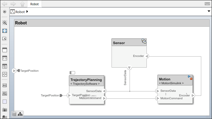
Open the architecture model of a robot arm that consists of sensors, motion actuators, and a planning algorithm. You can use System Composer to view the interfaces and manage the requirements for this model.
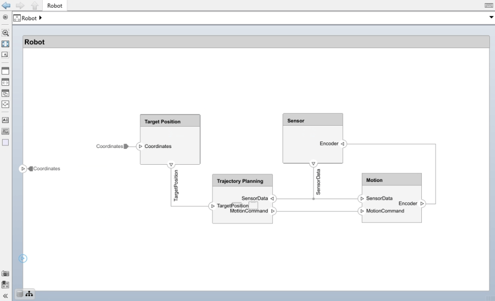
Reference Simulink Behavior Model in Component
When a component does not require further architectural decomposition, you can enable model simulation and an end-to-end workflow. To enable model simulation, implement Simulink behaviors for components. You can associate a Simulink model with a component or link to an existing Simulink model or subsystem.
Select the
Motioncomponent. On the toolstrip, click Modeling > Component > Create Simulink Behavior.From the Type list, select
Model Reference. Provide the model nameMotionSimulink. The default name is the name of the component.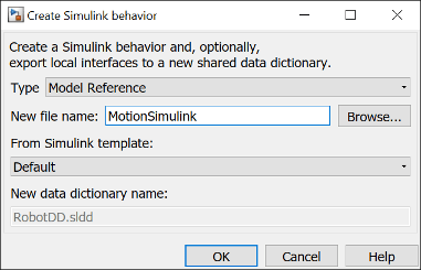
Click OK. A new Simulink model file with the provided name is created in the current folder. The root-level ports of the Simulink model reflect the ports of the component. The component in the architecture model is linked to the Simulink model. The
 icon on the component indicates that the component
has a Simulink behavior.
icon on the component indicates that the component
has a Simulink behavior.Note
To remove model behavior, select the linked
Motioncomponent and, on the toolstrip, click Modeling > Component > Inline Linked Model.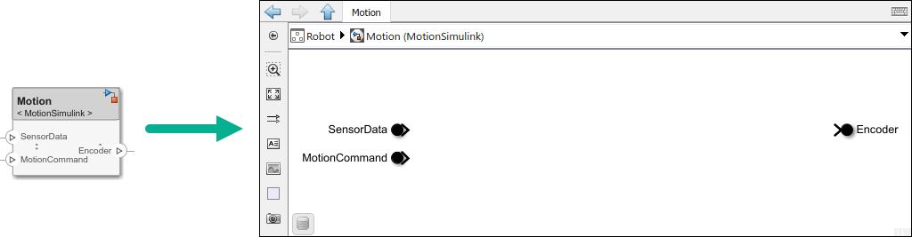
To view the interfaces on the SensorData port converted into Simulink bus elements, double-click the port in Simulink.
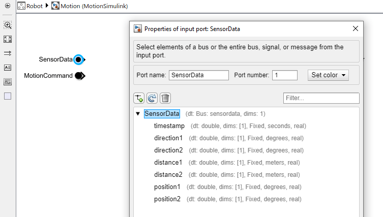
You can also link to an existing Simulink behavior model from a System Composer component, provided that the component is not already linked to a reference architecture. Select the component and, on the toolstrip, click Modeling > Component > Link to Different Model. You can type or browse for the name of a Simulink model.
You can also link a referenced Simulink subsystem behavior to a component. Use subsystem references to author Simulink or Simscape behaviors with physical ports, connections, and blocks.
Select the
Motioncomponent. On the toolstrip, click Modeling > Component > Create Simulink Behavior.From the Type list, select
Subsystem Reference. Provide the model nameMotionSubsystem. The default name is the name of the component.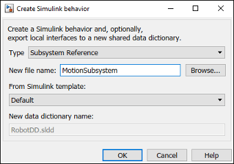
Click OK. A new Simulink subsystem file with the provided name is created in the current folder. The root-level ports of the Simulink subsystem reflect the ports of the component. The component in the architecture model is linked to the Simulink subsystem. The
 icon on the component indicates that the component
has a Simulink subsystem behavior.
icon on the component indicates that the component
has a Simulink subsystem behavior.
Add Stateflow Chart Behavior to Component
To implement event-based modeling with state machines, add Stateflow chart behavior to a component. State charts consist of a finite set of states with transitions between them to capture the modes of operation for the component. This functionality requires a Stateflow license.
A System Composer component with stereotypes, interfaces, requirement links, and ports, is preserved when you add Stateflow Chart (Stateflow) behavior.
Select the
Sensorcomponent. On the toolstrip, click Modeling > Component > Create Stateflow Chart Behavior.Double-click
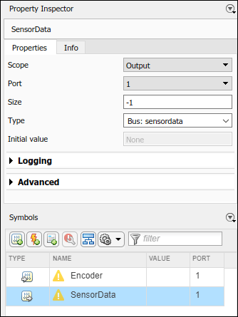
Sensor, which has the Stateflow icon. From the Modeling menu, click Symbols Pane to view the Stateflow symbols. The input port Encoder appears as input data in the symbols pane and the output port SensorData appears as output data.
Select the SensorData output and view the interface in the Property Inspector. You can access this interface like a Simulink bus signal.
Design Software Architecture in Component
To design a software architecture, define function execution order, simulate, and generate code, create a software architecture from a System Composer component.
Rename the
Trajectory Planningcomponent toTrajectoryPlanningso that it is a valid C variable name.Select the
TrajectoryPlanningcomponent. On the toolstrip, click Modeling > Component > Create Software Architecture Model.Specify the name of the software architecture as
TrajectorySoftware. Click OK.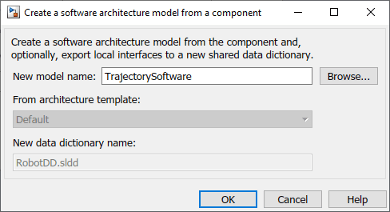
The software architecture model
TrajectorySoftware.slxis referenced from theTrajectoryPlanningcomponent.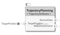
Double-click the
TrajectoryPlanningcomponent to interact with theTrajectorySoftwaresoftware component.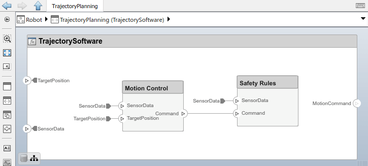
Add Activity Diagram Behavior to Component
To visualize a high-level decision making process, add activity diagram behavior to a component. An activity diagram contains activity nodes and flows. For more information, see Describe System Behavior Using Activity Diagrams. You can either create a new activity diagram behavior within a component or link the component to an existing activity diagram model.
Note
You cannot create an activity behavior for a component that has existing ports or subcomponents.
To create an activity diagram behavior, first delete the ports from the
Target Position component., and then take one of these
actions:
Select the
Target Positioncomponent. On the toolstrip, click Modeling > Component > Create Activity Diagram Behavior. This action opens a new activity diagram canvas.
To view and author the activity diagram, double-click the Target
Position component, which has the activity diagram icon.
After you design the activity diagram, the component displays input and output ports
that correspond to the parameter nodes within the activity diagram. Connect the output
port of the Target Position component to the input port of the
Trajectory Planning component.
You can also link to an existing activity diagram model. Select the component and, on the toolstrip, click Modeling > Component > Link to Different Model. For this example, you can use the
TargetPosition.slx model.
Represent System Interaction Using Sequence Diagrams
To represent the interaction between structural elements of an architecture as a sequence of message exchanges, use a sequence diagram in the Architecture Views Gallery.
Observe the robot arm architecture model consisting of components, ports, connections, and behaviors. The model simulation results must match the interactions within the sequence diagrams.
Create a new sequence diagram by navigating to Modeling > Sequence Diagram. The Architecture Views Gallery opens. To create a new sequence diagram, click
 New > Sequence Diagram.
A new sequence diagram called
SequenceDiagram1is created in the View Browser, and the Sequence Diagram tab becomes active. Under Sequence Diagram Properties, rename the sequence diagramRobotArmSequence.Select Component > Add Lifeline
 to add a lifeline. A new lifeline with no name is created and is indicated by a dotted line.
Click the down arrow and select
Sensor. Add a second lifeline namedMotion.Select the vertical dotted line for the
Sensorlifeline. Click and drag to theMotionlifeline. In the To box, start to typeSensordataand chooseSensorDatafrom the drop down menu. A message is created from the SensorData port on theSensorcomponent to the SensorData port on theMotioncomponent.Click on the message to see where to place the message condition. Enter a message trigger condition in the form:
rising(SensorData.distance1-1)
The signal name is a data element on a data interface. The message will be recognized at the zero-crossing event when the value of
SensorData.distance1rises to 1.


