Create Architecture Model with Interfaces and Requirement Links
In this topic, you learn how to create an architecture model of a robot arm using System Composer™, define interfaces on ports, and add requirement links to components.
You learn how to:
Start System Composer.
Add architectural components to represent robot arm sensors, trajectory planning, and its motion.
Create ports and connections to represent data exchange.
Define data interfaces to represent the structure of data.
Manage requirement links to represent connections to requirements from model elements.
A Requirements Toolbox™ license is required to link, trace, and manage requirements in System Composer.
For more information about the model-based systems engineering workflow within System Composer, see Compose and Analyze Systems Using Architecture Models.
Visually Represent System
Implementing an architectural design starts with visually representing the system using components and their connections. Create an architecture model, represent the system components, and draw the connections between them.
Create Architecture Model
Enter this command in the MATLAB® Command Window.
systemcomposer
The Simulink® Start Page opens to System Composer.
Click Architecture Model.
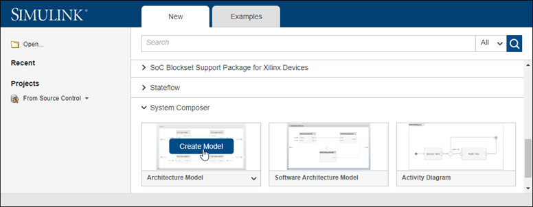
System Composer provides template architecture models that address different domains in systems engineering and software architecture modeling: Architecture Model and Software Architecture Model. All architecture models provide the same structural capabilities with some domain and platform specific constraints. For more information on architecture templates, see Choose Architecture Template for System Design.
A new, blank architecture model canvas opens. You can identify an architecture model by the badge in the lower left corner and the component palette on the left side.

Double-click the architecture model header and change
untitledto a descriptive model name, for example,RobotDesign. The name of the model generally reflects the system whose architecture you are building.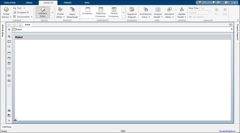
Save the model.
Draw Components
Design a mobile robotic arm where a sensor senses position and trajectory planning computes a path to a location that the robot needs to reach using motion. An architecture model of such a system could consist of three primary components: Sensors, Trajectory Planning, and Motion. You can represent these components in System Composer using three Component blocks.
Click and drag a Component block
 from the left-side palette.
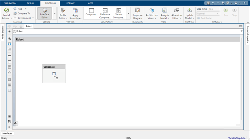
Rename the component as
Sensors.Follow these steps to create
Trajectory PlanningandMotioncomponents.
Create Ports and Connections
You can begin to create connectivity between components by describing the flow of power, energy, data, or any other representative information. Create ports on the components that provide or consume information and connectors that bind two component ports to represent the flow of the information.
You can add a port to a component on any side, and the port can have either an input or output direction. To create a port, pause your cursor over a component side. Click and release to view port options. Select either Input, Output, or Physical to create a port. Rename the port using a name that represents the information that flows through that port.
Create an output port on the bottom side of the Sensors component. Rename it SensorData.
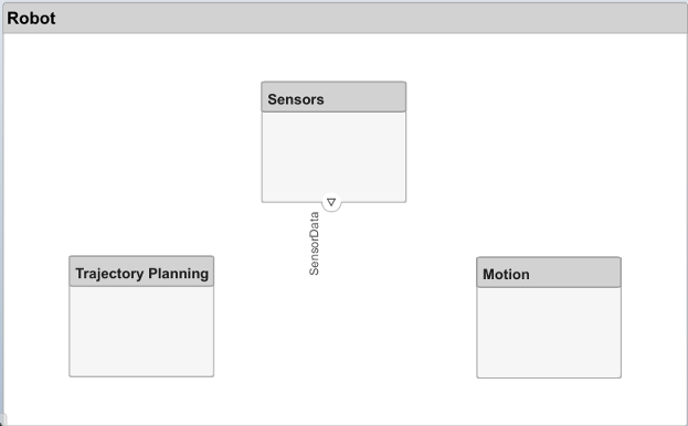
Click and drag a line from the SensorData output port to the
Motioncomponent. When you see an input port created at the component side, release the pointer. By default, this new port has the same name as the source port.Pause on the corner of the SensorData line until you see the branch icon
 . Right-click and drag a branch line to the
 Trajectory Planningcomponent.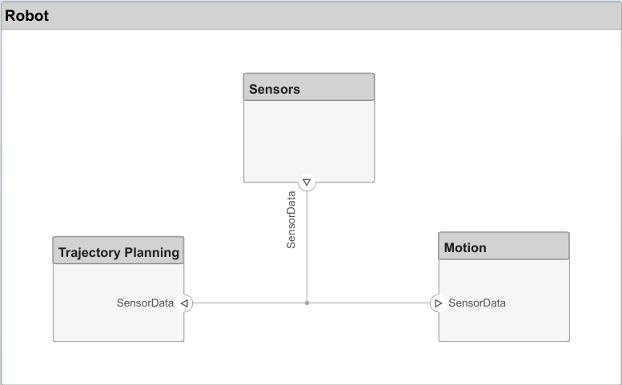
Complete the connections as shown in this figure.

The root level of the architecture model can also have ports that describe the interaction of the system with its environment. In this example, the target position for the robot is provided by a computer external to the robot itself. Represent this relationship with an input port.
Click the left edge of the architecture model and enter the port name TargetPosition.
Connect an architecture port to a component by dragging a line from the TargetPosition input port to the
Trajectory Planningcomponent. Connections to or from an architecture port appear as tags.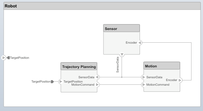
Edit Data Interfaces
You can define a data interface to fully specify a connection and its associated ports. A data interface can consist of multiple data elements with various dimensions, units, and data types. To check for consistency when connecting a port, you can also associate interfaces with unconnected ports during component design.
Specify the information flow through a port between components by configuring the data interface with attributes. A data interface can be as simple as sending an integer value, but it can also be a set of numbers, an enumeration, a combination of numbers and strings, or a bundle of other predefined interfaces.
Consider the data interface between the Sensors and the Motion components. The sensor data consists of:
Position data from two motors
Obstacle proximity data from two sensors
A time stamp to capture the freshness of the data
To open the Interface Editor, navigate to Modeling > Interface Editor.
Click the
 button to add a data interface. Name the interface
 sensordata.The data interface is named and defined separately from a component port and then assigned to a port.
Click the SensorData output port on the
Sensorscomponent. In the Interface Editor, right-clicksensordataand select Assign to Selected Port(s).If you click
sensordataagain, the three SensorData ports are highlighted, indicating the connected ports are associated with that interface.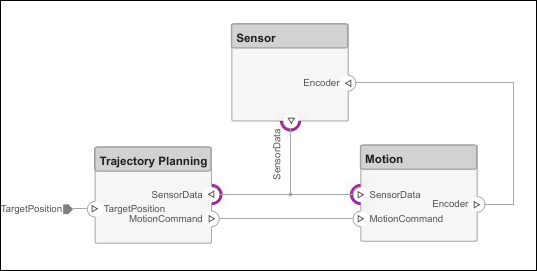
Add a data element to the selected data interface. Click the
 button to add a data element and name it
 timestamp.Continue adding data elements to the data interface as specified by clicking the add data element button.
Name Type Units timestampdoublesecondsdirection1doubledegreesdirection2doubledegreesdistance1doublemetersdistance2doublemetersposition1doubledegreesposition2doubledegreesEdit the properties of a data element in the Interface Editor. Click on the cell corresponding to the data element in the table and add units as shown in the specification.
Click the drop-down list next to the
 button to save the data interface to a data dictionary. A data dictionary allows you to collectively manage and share a set of interfaces among models. For instance, later in the design, if you choose to model the external computer as a separate architecture model, then this model and the
 Robotmodel can share the same data dictionary. Here, the dictionary is saved asRobotDD.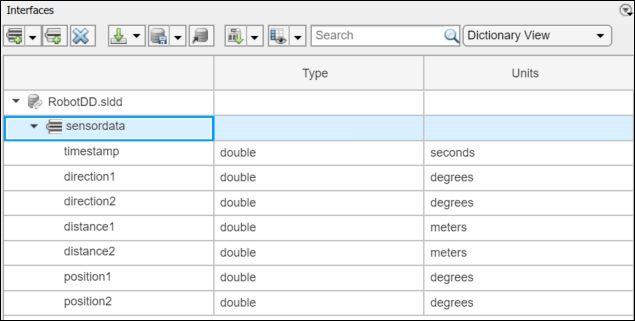
Decompose Components
Each component can have its own architecture. Double-click a component to decompose it into its subcomponents.
Double-click the
Trajectory Planningcomponent. The Explorer Bar and Model Browser indicates the position of the component in the model hierarchy.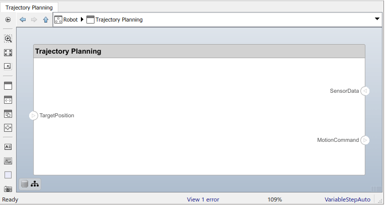
This component first uses the motor position data that is part of the
sensordatainterface to compute the ideal position and velocity command. It then processes the obstacle distance information in the same interface to condition this motion command according to some safety rules.Add
Motion ControlandSafety Rulescomponents as part of theTrajectory Planningarchitecture.Drag the TargetPosition port to the
Motion Controlcomponent. Add a Command output port toMotion Control, then drag a line to theSafety Rulescomponent. Drag lines from the SensorData port to theMotion ControlandSafety Rulescomponents.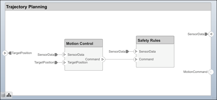
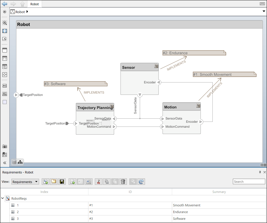
Robot Arm Architecture Model
Open the architecture model of a robot arm that consists of sensors, motion actuators, and a planning algorithm. You can use System Composer to view the interfaces and manage the requirements for this model.

Manage Requirement Links
Requirements are integral to the systems engineering process. Some requirements relate to the functionality of the overall system, and some relate to aspects of performance such as power, size, and weight. Decomposing high-level requirements into low-level requirements and deriving additional requirements is crucial to defining the architecture of the overall system. For instance, the overall power consumption of the robot determines the requirement for the power consumption of the robot controller.
To allocate and trace requirements with system elements, System Composer fully integrates with Requirements Toolbox. To derive appropriate requirements, you must sometimes analyze and specify properties (such as power) for elements of the system including components, ports, or connectors. For example, if the total cost of the system is a concern, a unitPrice property is necessary.
Manage requirements from the Requirements Perspective in System Composer using Requirements Toolbox. Navigate to Apps > Requirements Manager. For more information, see View and Link Requirements in Simulink (Requirements Toolbox).
To enhance the traceability of requirements, link requirements to architectural components and ports. When you click a component in the Requirements Perspective, linked requirements are highlighted. Conversely, when you click a requirement, the linked components are shown. To directly create a link, drag a requirement onto a component or a port.