Main Content

Synchronous Machine Model 1.0

Synchronous machine with field circuit and no damper

  • Synchronous Machine Model 10 block

Libraries:
Simscape / Electrical / Electromechanical / Synchronous

Description

The Synchronous Machine Model 1.0 block uses a simplified parameterization model for synchronous machines. Use the block to model synchronous machines with a field winding and no dampers.

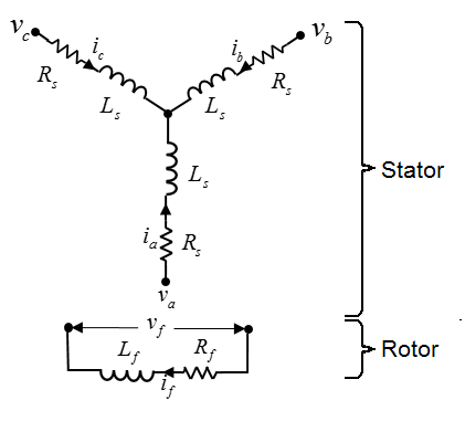
The figure shows the equivalent electrical circuit for the stator and rotor windings.

You can also model the stator windings either in a delta-wound or in an open-end configuration by setting Winding type to Delta-wound or Open-end, respectively.

Motor Construction

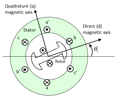
The diagram shows the motor construction with a single pole pair on the rotor. For the axes convention, when rotor mechanical angle θr is zero, the a-phase and rotor magnet fluxes are aligned. The block supports a second rotor axis definition for which rotor mechanical angle is defined as the angle between the a-phase magnetic axis and the rotor q-axis.

Equations

Voltages across the stator windings are defined by

[vavbvc]=[Rs000Rs000Rs][iaibic]+[dψadtdψbdtdψcdt],

where:

  • va, vb, and vc are the individual phase voltages across the stator windings.

  • Rs is the equivalent resistance of each stator winding.

  • ia, ib, and ic are the currents flowing in the stator windings.

  • dψadt,dψbdt, and dψcdt are the rates of change of magnetic flux in each stator winding.

The voltage across the field winding is expressed as

vf=Rfif+dψfdt,

where:

  • vf is the individual phase voltage across the field winding.

  • Rf is the equivalent resistance of the field winding.

  • if is the current flowing in the field winding.

  • dψfdt is the rate of change of magnetic flux in the field winding.

The excitation winding and the three star-wound stator windings contribute to the flux linking each winding. The total flux is defined by

[ψaψbψc]=[LaaLabLacLbaLbbLbcLcaLcbLcc][iaibic]+[LamfLbmfLcmf]if,

where:

  • ψa, ψb, and ψc are the total fluxes linking each stator winding.

  • Laa, Lbb, and Lcc are the self-inductances of the stator windings.

  • Lab, Lac, Lba, Lbc, Lca, and Lcb are the mutual inductances of the stator windings.

  • Lamf, Lbmf, and Lcmf are the mutual inductances of the field winding.

The inductances in the stator windings are functions of rotor electrical angle and are defined by

θe=Nθr+rotoroffset

Laa=Ls+Lmcos(2θe),

Lbb=Ls+Lmcos(2(θe2π/3)),

Lcc=Ls+Lmcos(2(θe+2π/3)),

Lab=Lba=MsLmcos(2(θe+π/6)),

Lbc=Lcb=MsLmcos(2(θe+π/62π/3)),

Lca=Lac=MsLmcos(2(θe+π/6+2π/3)),

where:

  • N is the number of rotor pole pairs.

  • θr is the rotor mechanical angle.

  • θe is the rotor electrical angle.

  • rotor offset is 0 if you define the rotor electrical angle with respect to the d-axis, or -pi/2 if you define the rotor electrical angle with respect to the q-axis.

  • Ls is the stator self-inductance per phase. This value is the average self-inductance of each of the stator windings.

  • Lm is the stator inductance fluctuation. This value is the fluctuation in self-inductance and mutual inductance with changing rotor angle.

  • Ms is the stator mutual inductance. This value is the average mutual inductance between the stator windings.

The magnetization flux linking winding, a-a’ is a maximum when θe = 0° and zero when θe = 90°. Therefore:

Lmf=[LamfLbmfLcmf]=[LmfcosθeLmfcos(θe2π/3)Lmfcos(θe+2π/3)]

and

Ψf=Lfif+LmfT[iaibic],

where:

  • Lmf is the mutual field armature inductance.

  • ψf is the flux linking the field winding.

  • Lf is the field winding inductance.

  • [Lmf]T is the transform of the Lmf vector, that is,

    [Lmf]T=[LamfLbmfLcmf]T=[LamfLbmfLcmf].

Simplified Equations

Applying the Park transformation to the block electrical defining equations produces an expression for torque that is independent of rotor angle.

The Park transformation is defined by

P=2/3[cosθecos(θe2π/3)cos(θe+2π/3)sinθesin(θe2π/3)sin(θe+2π/3)0.50.50.5]

Applying the Park transformation to the first two electrical defining equations produces equations that define the block behavior:

vd=Rsid+Lddiddt+LmfdifdtNωiqLq,

vq=Rsiq+Lqdiqdt+Nω(idLd+ifLmf),

v0=Rsi0+L0di0dt

vf=Rfif+Lfdifdt+32Lmfdiddt,

T=32N(iq(idLd+ifLmf)idiqLq),

and

Jdωdt=T=TLBmω.

where:

  • vd, vq, and v0 are the d-axis, q-axis, and zero-sequence voltages. These voltages are defined by

    [vdvqv0]=P[vavbvc].

  • id, iq, and i0 are the d-axis, q-axis, and zero-sequence currents, defined by

    [idiqi0]=P[iaibic].

  • Ld is the stator d-axis inductance. Ld = Ls + Ms + 3/2 Lm.

  • ω is the mechanical rotational speed.

  • Lq is the stator q-axis inductance. Lq = Ls + Ms − 3/2 Lm.

  • L0 is the stator zero-sequence inductance. L0 = Ls – 2Ms.

  • T is the rotor torque. For the Synchronous Machine Model 1.0 block, torque flows from the machine case (block conserving port C) to the machine rotor (block conserving port R).

  • J is the rotor inertia.

  • TL is the load torque.

  • Bm is the rotor damping.

Model Thermal Effects

You can expose thermal ports to model the effects of losses that convert power to heat. To expose the thermal ports, set the Modeling option parameter to either:

  • No thermal port — The block contains expanded electrical conserving ports associated with the stator windings, but does not contain thermal ports.

  • Show thermal port — The block contains expanded electrical conserving ports associated with the stator windings and thermal conserving ports for each of the windings and for the rotor.

For more information about using thermal ports in actuator blocks, see Simulating Thermal Effects in Rotational and Translational Actuators.

Variables

To set the priority and initial target values for the block variables before simulation, use the Initial Targets section in the block dialog box or Property Inspector. For more information, see Set Priority and Initial Target for Block Variables.

Nominal values provide a way to specify the expected magnitude of a variable in a model. Using system scaling based on nominal values increases the simulation robustness. You can specify nominal values using different sources, including the Nominal Values section in the block dialog box or Property Inspector. For more information, see System Scaling by Nominal Values.

Examples

Assumptions

Flux distribution is sinusoidal.

Ports

Conserving

expand all

Mechanical rotational conserving port associated with the machine rotor.

Mechanical rotational conserving port associated with the machine case.

Expandable three-phase port associated with the stator windings.

Dependencies

To enable this port, set Electrical connection to Composite three-phase ports and Winding type to Wye-wound or Delta-wound.

Electrical conserving port associated with a-phase.

Dependencies

To enable this port, set Electrical connection to Expanded three-phase ports and Winding type to Wye-wound or Delta-wound.

Electrical conserving port associated with b-phase.

Dependencies

To enable this port, set Electrical connection to Expanded three-phase ports and Winding type to Wye-wound or Delta-wound.

Electrical conserving port associated with c-phase.

Dependencies

To enable this port, set Electrical connection to Expanded three-phase ports and Winding type to Wye-wound or Delta-wound.

Since R2024a

Expandable three-phase port associated with the stator positive-end connections.

Dependencies

To enable this port, set Electrical connection to Composite three-phase ports and Winding type to Open-end.

Since R2024a

Expandable three-phase port associated with the stator negative-end connections.

Dependencies

To enable this port, set Electrical connection to Composite three-phase ports and Winding type to Open-end.

Since R2024a

Electrical conserving port associated with the a positive-end connection.

Dependencies

To enable this port, set Electrical connection to Expanded three-phase ports and Winding type to Open-end.

Since R2024a

Electrical conserving port associated with the b positive-end connection.

Dependencies

To enable this port, set Electrical connection to Expanded three-phase ports and Winding type to Open-end.

Since R2024a

Electrical conserving port associated with the c positive-end connection.

Dependencies

To enable this port, set Electrical connection to Expanded three-phase ports and Winding type to Open-end.

Since R2024a

Electrical conserving port associated with the a negative-end connection.

Dependencies

To enable this port, set Electrical connection to Expanded three-phase ports and Winding type to Open-end.

Since R2024a

Electrical conserving port associated with the b negative-end connection.

Dependencies

To enable this port, set Electrical connection to Expanded three-phase ports and Winding type to Open-end.

Since R2024a

Electrical conserving port associated with the c negative-end connection.

Dependencies

To enable this port, set Electrical connection to Expanded three-phase ports and Winding type to Open-end.

Electrical conserving port associated with the neutral phase.

Dependencies

To enable this port, set Winding type to Wye-wound and Zero sequence to Include.

Electrical conserving port associated with the field winding positive terminal.

Electrical conserving port associated with the field winding negative terminal.

Thermal conserving port associated with winding A.

Dependencies

To enable this port, set Modeling option to Show thermal port.

Thermal conserving port associated with winding B.

Dependencies

To enable this port, set Modeling option to Show thermal port.

Thermal conserving port associated with winding C.

Dependencies

To enable this port, set Modeling option to Show thermal port.

Thermal conserving port associated with the rotor.

Dependencies

To enable this port, set Modeling option to Show thermal port.

Parameters

expand all

Whether to enable the thermal ports of the block and model the effects of losses that convert power to heat.

Main

Whether to have composite or expanded three-phase ports.

Since R2024a

Select the configuration for the windings:

  • Wye-wound — The windings are wye-wound.

  • Delta-wound — The windings are delta-wound. The a-phase is connected between ports a and b, the b-phase between ports b and c and the c-phase between ports c and a.

  • Open-end — The windings are in an open-end configuration. The block exposes each end of the windings as electrical connections.

Select the modeling fidelity:

  • Constant Ld, Lq, Lmf and LfLd, Lq, Lmf, Lf, and PM values are constant and defined by their respective parameters.

  • Tabulated Ld, Lq, Lmf and LfLd, Lq, Lmf, Lf, and PM values are computed online from DQ and field currents look-up tables as follows:

    Ld=f1(id,iq,if)

    Lq=f2(id,iq,if)

    Lmf=f3(id,iq,if)

    Lf=f4(if)

Dependencies

This parameter is visible only when you set the Stator parameterization parameter to Specify Ld, Lq, and L0.

Number of permanent magnet pole pairs on the rotor.

Stator parameterization method.

Dependencies

The Stator parameterization setting affects the visibility of other parameters.

Direct-axis inductance of the machine stator.

Dependencies

This parameter is visible only when you set the Stator parameterization parameter to Specify Ld, Lq, and L0 and the Modeling fidelity parameter to Constant Ld, Lq, Lmf and Lf.

Quadrature-axis inductance of the machine stator.

Dependencies

This parameter is visible only when you set the Stator parameterization parameter to Specify Ld, Lq, and L0 and the Modeling fidelity parameter to Constant Ld, Lq, Lmf and Lf.

Direct-axis current vector, iD.

Dependencies

This parameter is visible only when you set the Stator parameterization parameter to Specify Ld, Lq, and L0 and the Modeling fidelity parameter to Tabulated Ld, Lq, Lmf and Lf.

Quadrature-axis current vector, iQ.

Dependencies

This parameter is visible only when you set the Stator parameterization parameter to Specify Ld, Lq, and L0 and the Modeling fidelity parameter to Tabulated Ld, Lq, Lmf and Lf.

Excitation current vector, iF.

Dependencies

This parameter is visible only when you set the Stator parameterization parameter to Specify Ld, Lq, and L0 and the Modeling fidelity parameter to Tabulated Ld, Lq, Lmf and Lf.

Ld matrix.

Dependencies

This parameter is visible only when you set the Stator parameterization parameter to Specify Ld, Lq, and L0 and the Modeling fidelity parameter to Tabulated Ld, Lq, Lmf and Lf.

Lq matrix.

Dependencies

This parameter is visible only when you set the Stator parameterization parameter to Specify Ld, Lq, and L0 and the Modeling fidelity parameter to Tabulated Ld, Lq, Lmf and Lf.

Mutual field armature inductance.

Dependencies

This parameter is visible only when you set the Stator parameterization parameter to Specify Ld, Lq, and L0 and the Modeling fidelity parameter to Tabulated Ld, Lq, Lmf and Lf.

Lf vector.

Dependencies

This parameter is visible only when you set the Stator parameterization parameter to Specify Ld, Lq, and L0, the Modeling fidelity parameter to Tabulated Ld, Lq, Lmf and Lf.

Zero-axis inductance for the machine stator.

Dependencies

This parameter is visible only if Stator parameterization is set to Specify Ld, Lq and L0 and Zero sequence is set to Include.

Average self-inductance of the three stator windings. This parameter must be:

  • Greater than 0.

  • Greater than the magnitude of the Stator inductance fluctuation, Lm.

  • Greater than the magnitude of the Stator mutual inductance, Ms.

Dependencies

This parameter is visible only if Stator parameterization is set to Specify Ls, Lm, and Ms.

Fluctuation in self-inductance and mutual inductance with the rotor angle.

Dependencies

This parameter is visible only if Stator parameterization is set to Specify Ls, Lm, and Ms.

Average mutual inductance between the stator windings.

Dependencies

This parameter is visible only if Stator parameterization is set to Specify Ls, Lm, and Ms.

Inductance of the field winding.

Dependencies

This parameter is visible only when you set the Stator parameterization parameter to Specify Ld, Lq, and L0 and the Modeling fidelity parameter to Constant Ld, Lq, Lmf and Lf or Stator parameterization parameter to Specify Ls, Lm, and Ms

Armature-field mutual inductance.

Dependencies

This parameter is visible only when you set the Stator parameterization parameter to Specify Ld, Lq, and L0 and the Modeling fidelity parameter to Constant Ld, Lq, Lmf and Lf or Stator parameterization parameter to Specify Ls, Lm, and Ms

Resistance of each of the stator windings.

Resistance of the field winding.

Zero-sequence model:

  • Include — Prioritize model fidelity. An error occurs if you Include zero-sequence terms for simulations that use the Partitioning solver. For more information, see Increase Simulation Speed Using the Partitioning Solver.

  • Exclude — Prioritize simulation speed for desktop simulation or real-time deployment.

Dependencies

If this parameter is set to:

  • Include and Stator parameterization is set to Specify Ld, Lq, and L0 — The Stator zero-sequence inductance, L0 parameter is visible.

  • Exclude — The Stator zero-sequence inductance, L0 parameter is not visible.

Mechanical

Inertia of the rotor.

Damping of the rotor.

Reference point for the rotor angle measurement. If you select the default value, the rotor and a-phase fluxes are aligned for a zero-rotor angle. Otherwise, an a-phase current generates the maximum torque value for a zero-rotor angle.

Thermal

To enable these parameters, set Modeling option to Show thermal port.

The temperature for which motor parameters are quoted.

Coefficient α in the equation relating resistance to temperature, as described in Thermal Model for Actuator Blocks. The default value is for copper.

The thermal mass value for the A, B, and C windings. The thermal mass is the energy required to raise the temperature by one degree.

The thermal mass of the rotor, that is, the energy required to raise the temperature of the rotor by one degree.

References

[1] Kundur, P. Power System Stability and Control. New York, NY: McGraw Hill, 1993.

[2] Anderson, P. M. Analysis of Faulted Power Systems. IEEE Press, Power Systems Engineering, 1995.

[3] Retif, J. M., X. Lin-Shi, A. M. Llor, and F. Morand “New hybrid direct-torque control for a winding rotor synchronous machine.” 2004 IEEE 35th Annual Power Electronics Specialists Conference. Vol. 2 (2004): 1438–1442.

[4] IEEE Power Engineering Society. IEEE Std 1110-2002. IEEE Guide for Synchronous Generator Modeling Practices and Applications in Power System Stability Analyses. Piscataway, NJ: IEEE, 2002.

Extended Capabilities

C/C++ Code Generation
Generate C and C++ code using Simulink® Coder™.

Version History

Introduced in R2018a

expand all