통신
예제를 통해 다양한 유형의 데이터 전송을 모델링하는 방법을 알아봅니다.
추천 예제

AM Radio Receiver
A simplified AM radio receiver. A single tone signal at 2kHz is transmitted with a carrier frequency of 600kHz. The variable capacitor, Cres, in the resonant circuit is used in order to sweep through a certain frequency span. When the resonance passes through 600kHz, the signal is picked up and amplified by a two-stage Class A RF power amplifier. The signal is finally extracted by a diode detector, where it would normally be passed on to an audio amplifier (not included here). The Scope displays the final output, the value of the resonant capacitance, and the received and amplified signals.

ARINC 429 Communication Link
A communication link that follows the ARINC 429 specification. Here it is configured for 100kBits per second operation. The ARINC 429 specification is for a simplex broadcast bus with odd parity checking. The cable is a balanced line comprising a twisted pair for data wires A and B, plus an outer shield. This model can be used to check compliance with the ARINC 429 specification, and to assess the impact of different cable lengths, cable parameters and abstracted transmitter and receiver characteristics. It can also be used to check operation with multiple receivers, the ARINC 429 specification allowing for up to 20 receivers to connect to a single transmitter.
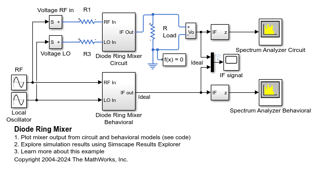
Diode Ring Mixer
How a diode ring can be used to demodulate a frequency-modulated signal. The RF input has a fixed frequency of 9MHz, and the local oscillator has a fixed frequency of 11MHz. Hence the frequency-modulated signal is a sine wave of 2MHz. This 2MHz component is clearly visible in the IF response. The second component in the IF response is the sum of the RF and local oscillator frequencies i.e. 20MHz.
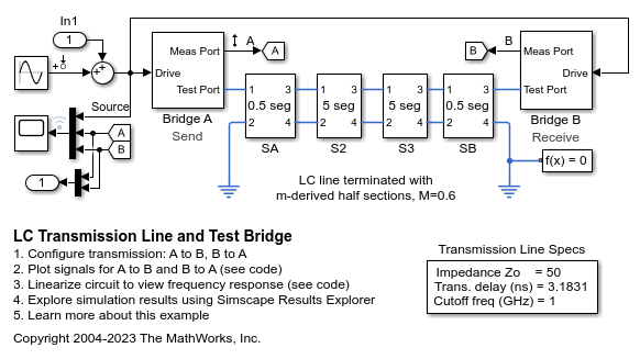
LC Transmission Line and Test Bridge
A transmission line model and bi-directional test bridge. Reflected and transmitted signals are slightly different if the test direction is changed. This is because the line model is not symmetric. This type of model can be used both to explore the impact of cable choice on transmission characteristics, and also to compare relative fidelity of different transmission line model structures and parameterizations.
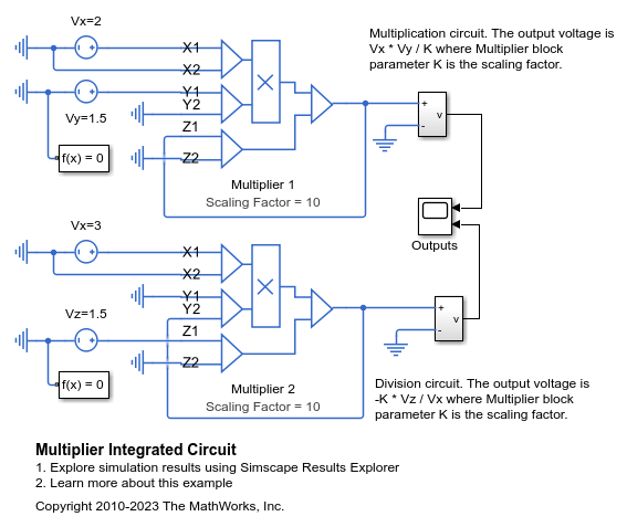
곱셈기 집적 회로
이 모델은 Multiplier 블록을 사용하여 두 입력 전압을 곱하거나 나누는 방법을 보여줍니다. 두 가지 모두 최종 전압에 도달할 때까지 슬루 레이트 제한이 발생합니다. 또한, 솔버가 모든 노드에 대해 전압을 결정할 수 있도록 입력 측 회로에 Electrical Reference 블록이 있어야 합니다.
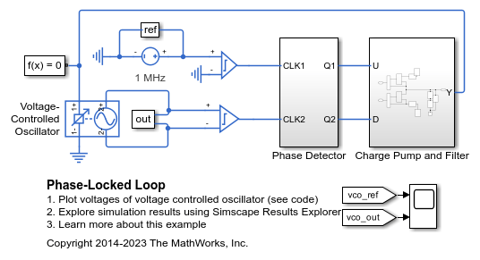
위상 고정 루프
이 예제는 위상 고정 루프를 모델링하는 방법을 보여줍니다. 충전 펌프(charge pump)와 필터는 개별 아날로그 컴포넌트를 사용하여 모델링되는 반면, 발진기는 Simscape™ Electrical™ Voltage-Controlled Oscillator 블록을 사용하여 동작 컴포넌트로 표현됩니다. 위상 검출기의 D 유형 플립플롭은 동작을 정의하는 Simulink® 블록을 사용하여 간소화된 형태로 표현되고, 전기 컴포넌트는 인터페이스에서만 사용됩니다. 위상이 다른 상태로 VCO를 시작한 후 추종 기능을 테스트하기 위해 C1과 C2에 0이 아닌 초기 조건이 적용됩니다.
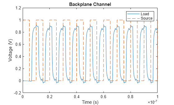
Simulate Backplane Channel in Simscape Using S-Parameters
Simulate a differential high-speed backplane channel in Simscape™ using the S-Parameter Rational Fit block. You compare the output of a simulated electrical model for different values of the Rational fit object parameter.