증폭기
예제를 통해 다양한 유형의 증폭기를 모델링하는 방법을 알아봅니다.
추천 예제
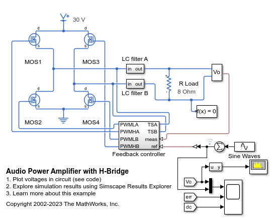
Audio Power Amplifier with H-Bridge
An H-bridge configuration switching audio power amplifier circuit. Switching audio power amplifiers are more efficient than conventional power amplifiers as switching devices are operating only in the fully-on and fully-off states. This audio power amplifier uses a 1MHz switching frequency and has a PI feedback controller to ensure that output voltage tracks the 2kHz and 2.5kHz sine wave inputs. The power spectrum is plotted in the Spectrum Analyzer, and can be used to inform selection of controller and filter parameters.
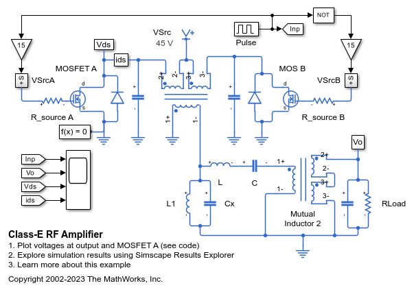
Class-E RF Amplifier
A class-E RF amplifier with circuit parameters chosen for an 80m wavelength. Class-E amplifiers achieve high efficiency levels as the MOSFETs never have simultaneously high Vds and Ids. The load network is used to shape the voltage and current waveforms. This model can be used to verify correct operation and to support component selection. Correct operation of the circuit is particularly sensitive to source resistance, R_source. The capacitance parameters for the two MOSFETs are representative for an FQA11N90 device.

Differential Pair Amplifier
A differential pair amplifier circuit. The circuit can be used to explore the properties of a differential pair amplifier. The model can be tested using differential and common-mode inputs. The balanced output has zero gain in common-mode provided that the two transistors have identical properties.
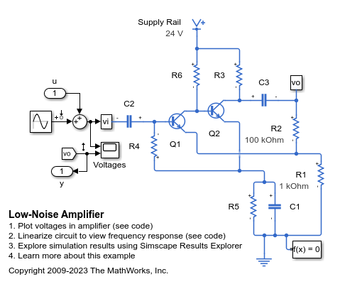
Low-Noise Amplifier
A typical low-noise audio amplifier circuit. Resistor R2 provides negative feedback to stabilize the overall amplifier gain, making it independent of transistor open-loop forward transfer gain. Circuit gain is approximately defined by (R1+R2)/R1 = 101. The simulation shows that it takes the circuit a few seconds to settle to its steady operating point, and that the output is initially clipped. Input u and output y are included to support linearization.

잡음이 있는 연산 증폭기 모델링하기
이 예제에서는 잡음을 전기 시뮬레이션에 통합하는 방법을 보여줍니다. 이 회로는 고주파 롤오프 주파수가 10MHz인 증폭기를 모델링합니다. Band-Limited Op-Amp 블록은 잡음을 추가합니다. Voltage Source 블록 Vn은 등가 전압 잡음 밀도를 20 nV/Hz^0.5으로 지정합니다. 또한 두 Resistor 블록의 잡음 모드 파라미터를 Enabled로 설정하여 저항기 R1과 R2의 열 잡음을 추가할 수도 있습니다. 하지만 잡음 소스를 서로 다르게 조합하여 이 모델을 실행하면 잡음의 주요 소스가 등가 잡음 전압임을 알 수 있습니다.
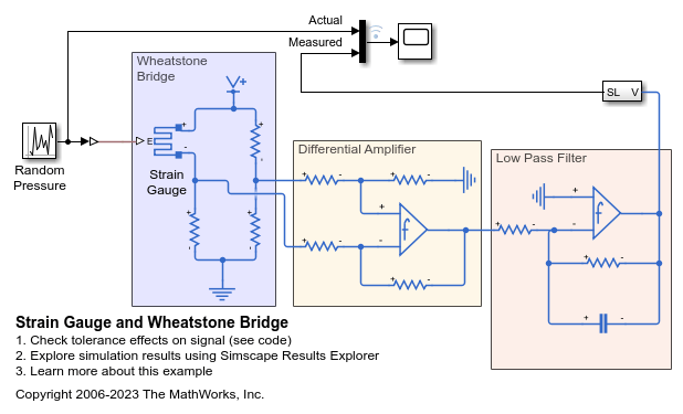
변형률 게이지 및 휘트스톤 브리지
이 모델은 변형률 게이지와 측정 증폭기를 모델링하는 방법을 보여줍니다. 변형률 게이지는 차동 증폭기에 연결되는 휘트스톤 브리지의 한 레그를 형성합니다. 그런 다음 두 번째 op-amp를 통해 측정 신호가 증폭되고 저역통과 필터가 적용됩니다. 이 op-amp는 시스템 수준에서 모델링되며 사용자가 개루프 대역폭, 이득 및 최대 슬루 레이트 같은 파라미터를 지정하게 됩니다. 이 회로에서 동특성은 주로 저역통과 필터에 의해 설정됩니다. op-amp 대역폭과 최대 슬루 레이트는 계단 응답에 거의 영향을 미치지 않습니다.

RF Power Amplifier Characterization Test Harness
Defines a test harness to estimate a non-linear behavioral model of a RF power amplifier from a Simscape™ Electrical™ simulation model.
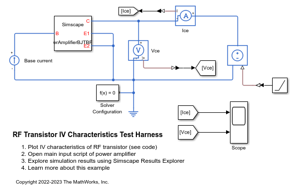
RF Transistor IV Characteristics Test Harness
Defines a test harness to estimate the I-V characteristics of a bipolar transistor from a Simscape™ Electrical™ simulation model.

스위칭 오디오 전력 증폭기
이 예제에서는 스위칭 오디오 전력 증폭기 회로를 보여줍니다. 스위칭 소자는 완전히 켜진 상태와 완전히 꺼진 상태에서만 동작하므로, 스위칭 오디오 전력 증폭기가 기존 전력 증폭기보다 효율적입니다. 이 오디오 전력 증폭기는 1MHz 스위칭 주파수를 사용하며, 출력 전압이 2kHz 및 2.5kHz 사인파 입력값을 추종하도록 PI 피드백 제어기를 포함하고 있습니다. 파워 스펙트럼은 스펙트럼 분석기에 플로팅되며, 제어기와 필터 파라미터의 선택에 대한 정보를 나타내는 데 사용할 수 있습니다.

