File Solid
Solid with properties derived from CAD file

Libraries:
Simscape /
Multibody /
Body Elements
Description
The File Solid block models a solid using geometry, inertia, color, and reference frame from a CAD file. The block supports various CAD formats listed in the Supported Software and File Formats section.
Supported Software and File Formats
| CAD | Release Supported |
|---|---|
| ACIS | Up to 2020 |
| Autodesk® Inventor | Up to 2022 |
| CATIA V4 | Up to 4.2.5 |
| CATIA V5 | Up to V5-6 R2021 |
| CATIA V6 | Up to V5-6 R2019(R29) |
| Creo-Pro/E | Pro/Engineer 19.0 to Creo 8.0 |
| IGES | 5.1, 5.2, and 5.3 |
| JT | Up to v10.5 |
| NX | V11.0 to NX 18.0, NX to NX12, NX 1847 Series to NX 1980 Series |
| OBJ | All Versions |
| Parasolid | Up to v33 |
| PRC | All Versions |
| Rhino3D | 4 to 7 |
| Solid Edge | V19 - 20, ST - ST10, 2021 |
| SolidWorks® | 97 to 2021 |
| STEP | AP 203 E1/E2, AP 214, and AP 242 |
| STL | All Versions |
| U3D | ECMA-363 |
Note
The block cannot read CAD drawings because they do not contain the necessary data for a solid.
Import Parts
The File Solid block represents the imported part as a rigid body. The block can read the inertia and color data from the CAD file. Alternatively, you can specify these properties explicitly for the imported parts. For details, see Inertia and Graphic.
By default, the block has only one reference frame that defines the position and
orientation of the solid. To create additional frames on the body, in the
Frames section, select the Create button
![]() .
.
By default, the imported body has only one reference frame that defines the position and orientation of the imported body. The position and orientation of the reference frame are consistent with the model origin in the original CAD file.
If you need to have the connection on a different part of the body or if you
need to have multiple connections on the body, you can create additional frames
on the body. Each frame adds a new frame port to the block. To create additional
frames on the body, in the Frames section, select the
Create button ![]() .
.
Import Assemblies
The File Solid block represents the imported assembly as a single rigid body using the default pose specified in the CAD file. The block ignores all the constraints in the CAD file and assumes that the whole assembly has one density.
The File Solid block can read density data from the
CAD file if you, under Inertia, specify
Type as Calculate From Geometry
and Based On as Density From File.
To ensure that the block successfully reads the density, the CAD file must have a
density for the whole assembly and the densities of all the parts must either have
the same value or be unspecified. Otherwise, the simulation returns an error.
You can manually specify the density, mass, or inertia properties of the imported assembly. The process is the same as the process for a single part.
You can import an assembly that has parts represented by different modeling methods, such as faceted, polygonal, and BRep models. However, you can create frames only on parts represented by BRep models because they have the necessary boundary primitives, such as points, edges, and faces.
Compute Inertia Properties
To compute the inertia properties of the solid, set the Inertia > Type parameter to
Calculate from Geometry. This setting exposes the
Inertia button in the toolstrip of the Property
Inspector. To compute the inertia properties, click the Inertia button and the
visualization pane displays the computed values.
![]()
The block defines the center of mass in the reference frame of the solid and specifies the moments and products of inertia in the inertia frame of resolution, which aligns its axes with the reference frame and positions its origin at the center of mass of the solid. For more information on specifying the inertia, see Specifying Custom Inertias.
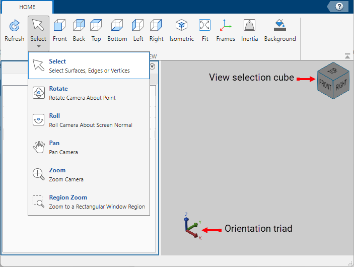
Visualize Solid
The Property Inspector includes a visualization pane that provides instant visual feedback on the solid. Use the pane to check and adjust the shape and color of the solid. To inspect the solid from different angles, select a standard view, interact with the view selection cube or orientation triad, or rotate, pan, and zoom the display.
To view the latest changes to the solid geometry in the visualization pane, in the toolstrip, click Refresh. You can also display the frames on the solid and change the background color of the visualization pane by clicking Frames and Background in the toolstrip.
Export Geometry
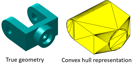
The File Solid block can generate a convex hull representation of an imported CAD file in the Simscape Multibody environment. For solids with concave features, the generated geometry is the smallest convex hull that fully encloses the solid. This convex hull serves as an approximation of the true geometry and can be used for spatial contact modeling. The figure shows a body and its convex hull representation.
The block calculates the physical properties, such as mass and inertia, based on the true geometry of a solid.
Examples
Cartesian 3-D Printer
Models a Cartesian 3-D printer. The model allows you to specify the rotational motion of the motor on each axis to define a printing path. In this example, the printing head moves along the edges of two letters, S and M, using the predefined rotational motions.

Tower Crane with Trolley and Hoist
Models a tower crane with a trolley and a hoist. The hoist can raise and lower a load, and the trolley moves the load towards and away from the tower. Blocks from the belts and cables library are used to model the pulleys that control lifting the load and moving the trolley.
Limitations
On Mac, the visualization pane runs slow if the generated geometry has a large number of triangles or vertices. To mitigate this issue, you can use CAD files with less vertices.
Ports
Frame
Geometry
Parameters
Geometry
CAD file name or path to CAD file, specified as a character vector. If the file name or path does not include a file extension, the block assumes the file type is STEP. The block supports various formats of CAD files. For a list of supported CAD file formats, see Supported Software and File Formats.
Depending on the location of the CAD file, use one of these methods to specify File Name.
| Location | Methods |
|---|---|
| File is in the current working folder or on the MATLAB® path | Enter the file name in the text box. Example:
|
| File is in a folder that is neither the current folder nor on the MATLAB path |
|
Tip
When using the block across multiple platforms or sharing the model with others, consider using either the file name or relative path.
A forward slash (/) is a valid separator on any platform. A backward slash (\) is valid only on Microsoft Windows platforms.
Source of the solid geometry units. Select From
File to use the units specified in the imported file.
Select Custom to specify your own
units.
Length units in which to interpret the geometry defined in a geometry file. Changing the units changes the scale of the imported geometry.
Dependencies
To enable this parameter, set Unit Type to
Custom.
Under Export, select Convex Hull to generate a convex hull representation of the true geometry. Select this parameter enables the port CH.
Inertia
Inertia parameterization to use. Select Point Mass to model a concentrated mass with negligible rotational inertia. Select Custom to model a distributed mass with the specified moments and products of inertia. The default setting, Calculate from Geometry, enables the block to automatically calculate the rotational inertia properties from the solid geometry and specified mass or mass density.
Parameter to use in inertia calculation. The block calculates the inertia tensor from the solid geometry and the parameter selected.
Density from File: The block calculates the inertia of the body based on the density obtained from the CAD file. Note that only some CAD formats contain density data.Custom Density: The block calculates the inertia of the body based on the density specified in the dialog box.Custom Mass: The block calculates the inertia of the body based on the mass specified in the dialog box.
Dependencies
To enable this parameter, set Type to
Calculate from Geometry.
Mass per unit volume of material. The value is a scalar with units of density and can be positive or negative. Specify a negative mass density to model the effects of a void or cavity in a solid body.
Dependencies
To enable this parameter, set:
Type to
Calculate from GeometryBased on to
Custom
                                            Density
Total mass to attribute to the solid element. This parameter can be positive or negative. Use a negative value to capture the effect of a void or cavity in a compound body (one comprising multiple solids and inertias), being careful to ensure that the mass of the body is on the whole positive.
Dependencies
To enable this parameter, set Type to
Custom or Point
Mass. Alternatively, set Type
to Calculate from Geometry and then set
Based on to Custom
Mass.
Graphic
Type of the visual representation of the solid, specified as From Geometry, Marker, or None. Set the parameter to From Geometry to show the visual representation of the solid. Set the parameter to Marker to represent the solid as a marker. Set the parameter to None to hide the solid in the model visualization.
Parameterizations for specifying visual properties.
Simple: Choose this option to define basic visual properties, including Diffuse Color and Opacity.Advanced: Choose this option to specify more visual properties, such as Specular Color, Ambient Color, Emissive Color, and Shininess.From File: Choose this option to use color data from the imported file. Only specific file formats, such asPro/E,STEP, andSLDPRT, support color data. For formats that do not support color data, the part defaults to black.
Dependencies
To enable this parameter, set Type to
From
                    Geometry
or
Marker.
Shape of the marker by means of which to visualize the solid. The motion of the marker reflects the motion of the solid itself.
Dependencies
To enable this parameter, set Type to Marker.
Width of the marker in pixels. This width does not scale with zoom level. Note that the apparent size of the marker depends partly on screen resolution, with higher resolutions packing more pixels per unit length, and therefore producing smaller icons.
Dependencies
To enable this parameter, set Type to Marker.
Color of the graphic under direct white light, specified as an [R G B] or [R G B A] vector on a 0–1 scale. An optional fourth element (A) specifies the color opacity on a scale of 0–1. Omitting the opacity element is equivalent to specifying a value of 1.
Dependencies
To enable this parameter, set Type to From
Geometry or Marker.
Color of the light due to diffuse reflection, specified as an [R,G,B] or [R,G,B,A] vector with values in the range of 0 to 1. The vector can be a row or column vector. The optional fourth element specifies the color opacity. Omitting the opacity element is equivalent to specifying a value of 1.
The diffuse color reflects the main color of the rendered solid and provides shading that gives the rendered object a three-dimensional appearance.
Dependencies
To enable this parameter, set:
Type to
From GeometryorMarker.Visual Properties to
Advanced.
Color of the light due to specular reflection, specified as an [R,G,B] or [R,G,B,A] vector with values in the range of 0 to 1. The vector can be a row or column vector. The optional fourth element specifies the color opacity. Omitting the opacity element is equivalent to specifying a value of 1. This parameter changes the color of the specular highlight, which is the bright spot on the rendered solid due to the reflection of the light from the light source.
Dependencies
To enable this parameter, set:
Type to
From GeometryorMarker.Visual Properties to
Advanced.
Color due to self illumination, specified as an [R,G,B] or [R,G,B,A] vector in the range of 0 to 1. The vector can be a row or column vector. The optional fourth element specifies the color opacity. Omitting the opacity element is equivalent to specifying a value of 1.
The emission color is color that does not come from any external source, and therefore seems to be emitted by the solid itself. When a solid has an emissive color, the solid can be seen even if there is no external light source.
Dependencies
To enable this parameter, set:
Type to
From GeometryorMarker.Visual Properties to
Advanced.
Frames
Select to expose the R port.
Click the Create button ![]() to open a pane for creating a new
body-attached frame. In this pane, you can specify the name, origin, and
orientation for the frame.
to open a pane for creating a new
body-attached frame. In this pane, you can specify the name, origin, and
orientation for the frame.
To name the custom frame, click the text field of the Frame Name parameter. The name identifies the corresponding port on the solid block and in the Model Tree pane of the Multibody Explorer.
To select the Frame Origin of the custom frame, use one of the following methods:
At Reference Frame Origin: Make the new frame origin coincident with the origin of the reference frame of the solid.
At Center of Mass: Make the new frame origin coincident with the center of mass of the solid.
Based on Geometric Feature: Make the new frame origin coincident with the center of the selected feature. Valid features include surfaces, lines, and points. Select a feature from the visualization pane, then click Use Selected Feature to confirm the location of the origin. The name of the origin location appears in the field below this option.
To define the orientation of the custom frame, under the Frame Axes section, select the Primary Axis and Secondary Axis of the custom frame and then specify their directions.
Use the following methods to select a vector for specifying the directions of the primary and secondary axes. The primary axis is parallel to the selected vector and constrains the remaining two axes to its normal plane. The secondary axis is parallel to the projection of the selected vector onto the normal plane.
Along Reference Frame Axis: Selects an axis of the reference frame of the solid.
Along Principal Inertia Axis: Selects an axis of the principal inertia axis of the solid.
Based on Geometric Feature: Selects the vector associated with the chosen geometry feature of the solid. Valid features include surfaces and lines. The corresponding vector is indicated by a white arrow in the visualization pane. You can select a feature from the visualization pane and then click Use Selected Feature to confirm the selection. The name of the selected feature appears in the field below this option.
Frames that you have created. N is a unique
identifying number for each custom frame.
Click the text field to edit the name of an existing custom frame.
Click the Edit button
 to edit other aspects of
the custom frame, such as origin and axes.
to edit other aspects of
the custom frame, such as origin and axes.Click the Delete button
 to delete the custom
frame.
to delete the custom
frame.
Dependencies
To enable this parameter, create a frame by clicking New Frame.