Define Model Reference Interfaces
The ports on a Model block correspond to blocks at the top level, or root level, of the referenced model. The ports can be input, output, or control ports.
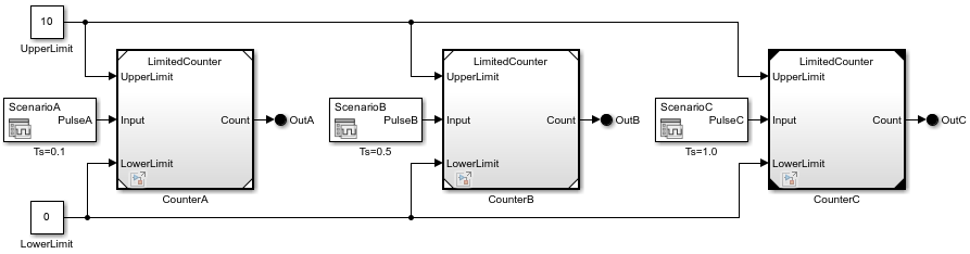
For example, in the MultiCounter model, each Model block references the
LimitedCounter model and has:
Three input ports, named UpperLimit, Input, and LowerLimit
One output port, named Count
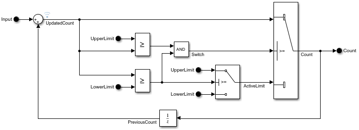
The LimitedCounter referenced model has:
Three input ports, named
UpperLimit,Input, andLowerLimitand represented by In Bus Element blocksOne output port, named
Countand represented by an Out Bus Element block
When you connect a signal to a Model block port, you connect the signal to the corresponding port of the referenced model.
The output of a Model block can differ despite the referenced model being the same.
For example, in MultiCounter, each Model block
Input port receives a signal from a unique Signal Editor
block. Because the input signal from each Signal Editor block uses a
different sample time, the output signal from each Model block differs
despite the referenced model being the same.
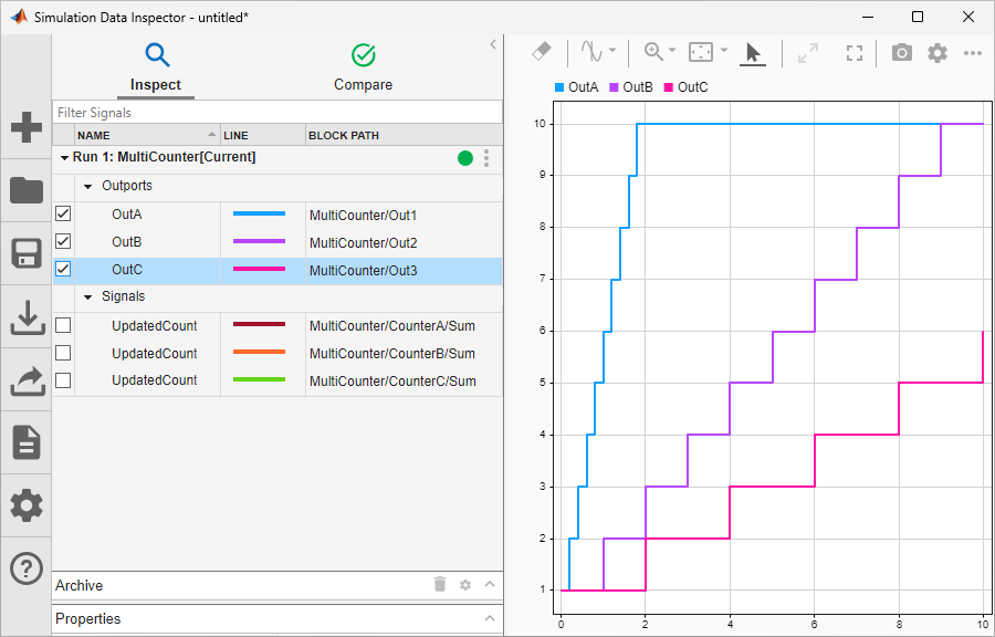
To view how the output signal for each Model block differs, use the Simulation Data Inspector.
Add Ports to Model Reference Interface
A model reference interface supports multiple types of ports and port blocks.
This table describes the type of ports and corresponding port blocks that a model reference interface supports.
| Type of Port | Corresponding Port Block |
|---|---|
| Signal port, input | Inport block |
| Signal port, output | Outport block |
| Bus element port, input | In Bus Element block |
| Bus element port, output | Out Bus Element block |
| Control port, enabled | Enable block |
| Control port, triggered | Trigger block |
| Control port, function-call | Trigger block with
Trigger type set to
function-call |
| Function port, client | Function Element Call block |
| Function port, server | Function Element block |
To add ports to a model reference interface, perform either of these actions:
In the top level of the referenced model, add blocks that correspond with ports.
In the parent model, add ports to a Model block that references the model.
Note
If the maximum port number in the model exceeds the number of ports in the model,
you cannot add ports to the model reference interface. For example, if there are five
port blocks in the model, and you change the port number parameter of one of them to
10, you cannot add ports to the model reference
interface.
To open a referenced model, open the model file or double-click the Model block. Then, add the port blocks to the referenced model.
To add ports to a Model block, pause on an edge of the block. When your pointer turns into a cross, click. A new port, highlighted in blue, appears on the edge you click.
Pause your pointer on the new port. In the action menu that expands, select the type of port you want to create. For example, you can create signal and bus element ports.
You can also add ports to a Model block by dragging a signal line from the model element you want to connect to an edge of the Model block.
Dragging from a port block creates a new port of the same type. Dragging from a Subsystem or Model block port that represents a port block also creates a new port of the same type as the port block.
The input signals for the Model block must be valid for the corresponding input blocks of the referenced model. The output signals for the Model block are the signals that connect to the corresponding output blocks.
To delete an existing port, select the port and press Delete. To delete multiple ports, press Shift, select the ports, and then press Delete.
For more information about referenced models with control ports, see Conditionally Execute Referenced Models.
Tip
You can use the same approach to add ports to and delete ports from Reference Component (System Composer) blocks and Component (AUTOSAR Blockset) blocks that are linked to models.
Refresh Model Blocks
Refreshing a Model block updates it to reflect changes to the interface of the referenced model. For example, when the referenced model gains or loses a port, refreshing the Model block updates its ports.
When you modify a referenced model while the parent model is open, the corresponding Model blocks automatically refresh.
When you modify a referenced model while the parent model is not open, the corresponding Model blocks refresh when you perform actions such as:
Loading the parent model
Selecting a Model block
Simulating the model hierarchy
Generating code for the model hierarchy
To manually refresh all Model blocks in the model hierarchy, perform either of these actions:
On the Model Block tab, click the Update Model button arrow. Then, select Refresh Blocks.
Use the
Simulink.BlockDiagram.refreshBlocksfunction.
To manually refresh Model blocks in a loaded and unopened model, use
the Simulink.ModelReference.refresh function.
Define Signal Attributes
Signal attributes in a referenced model are independent from the context of the Model block. For example, signal dimensions and data types do not propagate across the Model block boundary.
To define the attributes of input to a referenced model, use the parameters of the
root-level Inport and In Bus Element blocks. An In Bus
Element block can fully specify the hierarchy and attributes of an input bus
without a Simulink.Bus object.
In Bus Element and Out Bus Element blocks support
multirate virtual buses and do not require Simulink.Bus objects at model
interfaces, unlike Inport and Outport blocks.
For signals that connect to Outport blocks to propagate out of a referenced model to the parent model, the signal names must explicitly appear on the signal lines.
A referenced model can only provide input or get output for user-defined data types that
are fixed point or that Simulink.DataType or Simulink.Bus
objects define.
Use Buses at Model Interfaces
Bus input for a Model block must be consistent with the bus expected by the referenced model.
If you use a bus as an input to or an output from a referenced model:
Only a nonvirtual bus can contain variable-size signal elements.
For code generation, you can configure the
I/O arguments step
                        method
style of the C++ class interface for the referenced model only when using a nonvirtual bus or when using theDefaultstyle of the C++ class interface.For code generation, you can configure function prototype control for the referenced model only when using a nonvirtual bus.
For cleaner bus interfaces, use:
In Bus Element blocks instead of Inport blocks connected to Bus Selector blocks
Out Bus Element blocks instead of Bus Creator blocks connected to Outport blocks
For more information, see Simplify Subsystem and Model Interfaces with Bus Element Ports.
Log Signals in Referenced Models
In a referenced model, you can log any signal configured for signal logging. Use the Signal Logging Selector to select a subset or all the signals configured for signal logging in a model hierarchy. For details, see Override Signal Logging Settings.
You can use the Simulation Data Inspector to view and analyze signals logged in referenced models. You can view signals on multiple plots, zoom, and use data cursors to understand and evaluate the data. Also, you can compare signal data from multiple simulations. For an example of viewing signals in referenced models, see Component-Based Modeling with Model Reference.
Configure Sample Times
The first nonvirtual block that connects to a root-level input or output block of a referenced model must have the same sample time as the related port. If the sample times are different, use Rate Transition blocks to match input and output sample times, as shown in this block diagram.

Share Data Among Referenced Model Instances
By default, each Model block instance reads from and writes to a separate copy of the signals and block states in the model. Therefore, the instances do not interact with each other through shared signal or state data.
To share a piece of data between all of the instances (for example, an accumulator or a fault indicator), model the data as a data store.
To restrict access to data so that only the blocks in the referenced model can read from and write to it, use a Data Store Memory block in the model and select the Share across model instances parameter. For an example, see Share Data Among Multiple Instances of a Reusable Algorithm.
To allow access to data outside the referenced model, use a global data store, which is a
Simulink.Signalobject in the base workspace or a data dictionary. Data outside the referenced model can be in the parent model or in other referenced models.
For more information about data stores, see Model Global Data by Creating Data Stores.
See Also
Model | Inport | Outport | In Bus Element | Out Bus Element