Nonparametric Methods
The following sections discuss the periodogram, modified periodogram, Welch, and multitaper methods of nonparametric estimation, along with the related CPSD function, transfer function estimate, and coherence function.
Periodogram
In general terms, one way of estimating the PSD of a process is to simply find the discrete-time Fourier transform of the samples of the process (usually done on a grid with an FFT) and appropriately scale the magnitude squared of the result. This estimate is called the periodogram.
The periodogram estimate of the PSD of a signal of length L is
where Fs is the sampling frequency.
In practice, the actual computation of can be performed only at a finite number of frequency points, and usually employs an FFT. Most implementations of the periodogram method compute the -point PSD estimate at the frequencies
In some cases, the computation of the periodogram via an FFT algorithm is more efficient if the number of frequencies is a power of two. Therefore it is not uncommon to pad the input signal with zeros to extend its length to a power of two.
As an example of the periodogram, consider the following 1001-element signal xn, which consists of two sinusoids plus noise:
fs = 1000;                % Sampling frequency
t = (0:fs)/fs;            % One second worth of samples
A = [1 2];                % Sinusoid amplitudes (row vector)
f = [150;140];            % Sinusoid frequencies (column vector)
xn = A*sin(2*pi*f*t) + 0.1*randn(size(t));
% The three last lines are equivalent to
% xn = sin(2*pi*150*t) + 2*sin(2*pi*140*t) + 0.1*randn(size(t));
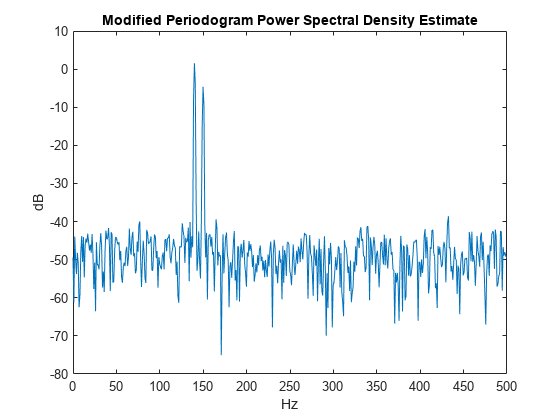
The periodogram estimate of the PSD can be computed using periodogram. In this case, the data vector is multiplied by a Hamming window to produce a modified periodogram.
[Pxx,F] = periodogram(xn,hamming(length(xn)),length(xn),fs);
plot(F,10*log10(Pxx))
xlabel('Hz')
ylabel('dB')
title('Modified Periodogram Power Spectral Density Estimate')
Algorithm
Periodogram computes and scales the output of the FFT to produce the power vs. frequency plot as follows.
If the input signal is real-valued, the magnitude of the resulting FFT is symmetric with respect to zero frequency (DC). For an even-length FFT, only the first (1 +
nfft/2) points are unique. Determine the number of unique values and keep only those unique points.Take the squared magnitudes of the unique FFT values. Scale the squared magnitudes (except for DC) by , where N is the length of signal prior to any zero padding. Scale the DC value by .
Create a frequency vector from the number of unique points, the
nfftand the sampling frequency.Plot the resulting magnitude squared FFT against the frequency.
Performance of the Periodogram
The following sections discuss the performance of the periodogram with regard to the issues of leakage, resolution, bias, and variance.
Spectral Leakage
Consider the PSD of a finite-length (length ) signal . It is frequently useful to interpret as the result of multiplying an infinite signal, , by a finite-length rectangular window, :
Because multiplication in the time domain corresponds to convolution in the frequency domain, the expected value of the periodogram in the frequency domain is
showing that the expected value of the periodogram is the convolution of the true PSD with the square of the Dirichlet kernel.
The effect of the convolution is best understood for sinusoidal data. Suppose that is composed of a sum of complex sinusoids:
Its spectrum is
which for a finite-length sequence becomes
The preceding equation is equal to
So in the spectrum of the finite-length signal, the Dirac deltas have been replaced by terms of the form , which corresponds to the frequency response of a rectangular window centered on the frequency .
The frequency response of a rectangular window has the shape of a periodic sinc:
L = 32;
[h,w] = freqz(rectwin(L)/L,1);
y = diric(w,L);

plot(w/pi,20*log10(abs(h)))
hold on
plot(w/pi,20*log10(abs(y)),'--')
hold off
ylim([-40,0])
legend('Frequency Response','Periodic Sinc')
xlabel('\omega / \pi')
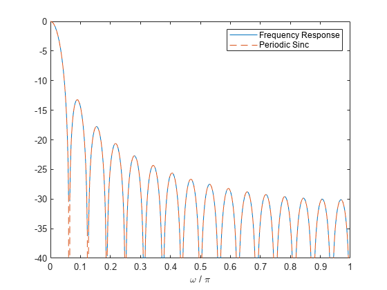
The plot displays a mainlobe and several sidelobes, the largest of which is approximately 13.5 dB below the mainlobe peak. These lobes account for the effect known as spectral leakage. While the infinite-length signal has its power concentrated exactly at the discrete frequency points , the windowed (or truncated) signal has a continuum of power "leaked" around the discrete frequency points .
Because the frequency response of a short rectangular window is a much poorer approximation to the Dirac delta function than that of a longer window, spectral leakage is especially evident when data records are short. Consider the following sequence of 100 samples:
fs = 1000;                 % Sampling frequency
t = (0:fs/10)/fs;          % One-tenth second worth of samples
A = [1 2];                 % Sinusoid amplitudes
f = [150;140];             % Sinusoid frequencies
xn = A*sin(2*pi*f*t) + 0.1*randn(size(t));
periodogram(xn,rectwin(length(xn)),1024,fs)
It is important to note that the effect of spectral leakage is contingent solely on the length of the data record. It is not a consequence of the fact that the periodogram is computed at a finite number of frequency samples.
Resolution
Resolution refers to the ability to discriminate spectral features, and is a key concept on the analysis of spectral estimator performance.
In order to resolve two sinusoids that are relatively close together in frequency, it is necessary for the difference between the two frequencies to be greater than the width of the mainlobe of the leaked spectra for either one of these sinusoids. The mainlobe width is defined to be the width of the mainlobe at the point where the power is half the peak mainlobe power (i.e., 3 dB width). This width is approximately equal to .
In other words, for two sinusoids of frequencies and , the resolvability condition requires that
In the example above, where two sinusoids are separated by only 10 Hz, the data record must be greater than 100 samples to allow resolution of two distinct sinusoids by a periodogram.
Consider a case where this criterion is not met, as for the sequence of 67 samples below:
fs = 1000;                  % Sampling frequency
t = (0:fs/15)/fs;           % 67 samples
A = [1 2];                  % Sinusoid amplitudes
f = [150;140];              % Sinusoid frequencies
xn = A*sin(2*pi*f*t) + 0.1*randn(size(t));
periodogram(xn,rectwin(length(xn)),1024,fs)
The above discussion about resolution did not consider the effects of noise since the signal-to-noise ratio (SNR) has been relatively high thus far. When the SNR is low, true spectral features are much harder to distinguish, and noise artifacts appear in spectral estimates based on the periodogram. The example below illustrates this:
fs = 1000;                  % Sampling frequency
t = (0:fs/10)/fs;           % One-tenth second worth of samples
A = [1 2];                  % Sinusoid amplitudes
f = [150;140];              % Sinusoid frequencies
xn = A*sin(2*pi*f*t) + 2*randn(size(t));
periodogram(xn,rectwin(length(xn)),1024,fs)
Bias of the Periodogram
The periodogram is a biased estimator of the PSD. Its expected value was previously shown to be
The periodogram is asymptotically unbiased, which is evident from the earlier observation that as the data record length tends to infinity, the frequency response of the rectangular window more closely approximates the Dirac delta function. However, in some cases the periodogram is a poor estimator of the PSD even when the data record is long. This is due to the variance of the periodogram, as explained below.
Variance of the Periodogram
The variance of the periodogram can be shown to be
which indicates that the variance does not tend to zero as the data length tends to infinity. In statistical terms, the periodogram is not a consistent estimator of the PSD. Nevertheless, the periodogram can be a useful tool for spectral estimation in situations where the SNR is high, and especially if the data record is long.
The Modified Periodogram
The modified periodogram windows the time-domain signal prior to computing the DFT in order to smooth the edges of the signal. This has the effect of reducing the height of the sidelobes or spectral leakage. This phenomenon gives rise to the interpretation of sidelobes as spurious frequencies introduced into the signal by the abrupt truncation that occurs when a rectangular window is used. For nonrectangular windows, the end points of the truncated signal are attenuated smoothly, and hence the spurious frequencies introduced are much less severe. On the other hand, nonrectangular windows also broaden the mainlobe, which results in a reduction of resolution.
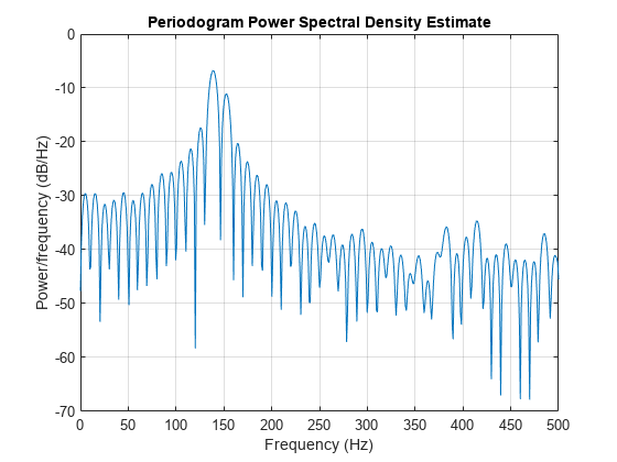
The periodogram allows you to compute a modified periodogram by specifying the window to be used on the data. For example, compare a default rectangular window and a Hamming window. Specify the same number of DFT points in both cases.
fs = 1000;                  % Sampling frequency
t = (0:fs/10)/fs;           % One-tenth second worth of samples
A = [1 2];                  % Sinusoid amplitudes
f = [150;140];              % Sinusoid frequencies
nfft = 1024;

xn = A*sin(2*pi*f*t) + 0.1*randn(size(t));
periodogram(xn,rectwin(length(xn)),nfft,fs)

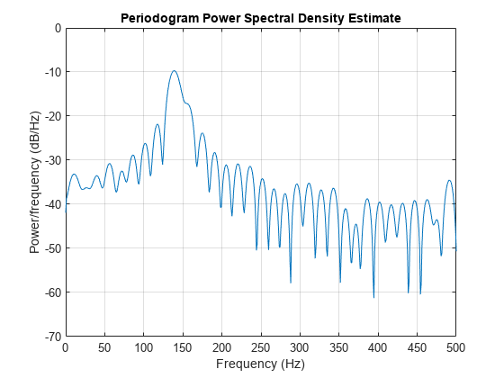
periodogram(xn,hamming(length(xn)),nfft,fs)
You can verify that although the sidelobes are much less evident in the Hamming-windowed periodogram, the two main peaks are wider. In fact, the 3 dB width of the mainlobe corresponding to a Hamming window is approximately twice that of a rectangular window. Hence, for a fixed data length, the PSD resolution attainable with a Hamming window is approximately half that attainable with a rectangular window. The competing interests of mainlobe width and sidelobe height can be resolved to some extent by using variable windows such as the Kaiser window.
Nonrectangular windowing affects the average power of a signal because some of the time samples are attenuated when multiplied by the window. To compensate for this, periodogram and pwelch normalize the window to have an average power of unity. This ensures that the measured average power is generally independent of window choice. If the frequency components are not well resolved by the PSD estimators, the window choice does affect the average power.
The modified periodogram estimate of the PSD is
where U is the window normalization constant:
For large values of L, U tends to become independent of window length. The addition of U as a normalization constant ensures that the modified periodogram is asymptotically unbiased.
Welch's Method
An improved estimator of the PSD is the one proposed by Welch. The method consists of dividing the time series data into (possibly overlapping) segments, computing a modified periodogram of each segment, and then averaging the PSD estimates. The result is Welch's PSD estimate. The toolbox function pwelch implements Welch's method.
The averaging of modified periodograms tends to decrease the variance of the estimate relative to a single periodogram estimate of the entire data record. Although overlap between segments introduces redundant information, this effect is diminished by the use of a nonrectangular window, which reduces the importance or weight given to the end samples of segments (the samples that overlap).
However, as mentioned above, the combined use of short data records and nonrectangular windows results in reduced resolution of the estimator. In summary, there is a tradeoff between variance reduction and resolution. One can manipulate the parameters in Welch's method to obtain improved estimates relative to the periodogram, especially when the SNR is low. This is illustrated in the following example.
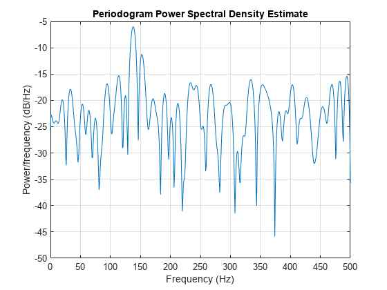
Consider a signal consisting of 301 samples:
fs = 1000;             % Sampling frequency
t = (0:0.3*fs)/fs;     % 301 samples
A = [2 8];             % Sinusoid amplitudes (row vector)
f = [150;140];         % Sinusoid frequencies (column vector)

xn = A*sin(2*pi*f*t) + 5*randn(size(t));
periodogram(xn,rectwin(length(xn)),1024,fs)
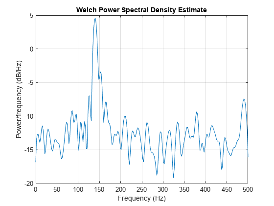
We can obtain Welch's spectral estimate for 3 segments with 50% overlap using a rectangular window.
pwelch(xn,rectwin(150),50,512,fs)
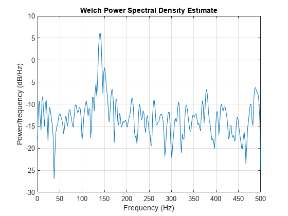
In the periodogram above, noise and the leakage make one of the sinusoids essentially indistinguishable from the artificial peaks. In contrast, although the PSD produced by Welch's method has wider peaks, you can still distinguish the two sinusoids, which stand out from the "noise floor."
However, if we try to reduce the variance further, the loss of resolution causes one of the sinusoids to be lost altogether.
pwelch(xn,rectwin(100),75,512,fs)
Bias and Normalization in Welch's Method
Welch's method yields a biased estimator of the PSD. The expected value of the PSD estimate is:
where L is the length of the data segments, U is the same normalization constant present in the definition of the modified periodogram, and W(f) is the Fourier transform of the window function. As is the case for all periodograms, Welch's estimator is asymptotically unbiased. For a fixed length data record, the bias of Welch's estimate is larger than that of the periodogram because the length of the segments is less than the length of the entire data sample.
The variance of Welch's estimator is difficult to compute because it depends on both the window used and the amount of overlap between segments. Basically, the variance is inversely proportional to the number of segments whose modified periodograms are being averaged.
Multitaper Method
The periodogram can be interpreted as filtering a length signal, , through a filter bank (a set of filters in parallel) of FIR bandpass filters. The 3 dB bandwidth of each of these bandpass filters can be shown to be approximately equal to . The magnitude response of each one of these bandpass filters resembles that of a rectangular window. The periodogram can thus be viewed as a computation of the power of each filtered signal (i.e., the output of each bandpass filter) that uses just one sample of each filtered signal and assumes that the PSD of is constant over the bandwidth of each bandpass filter.
As the length of the signal increases, the bandwidth of each bandpass filter decreases, making it a more selective filter, and improving the approximation of constant PSD over the bandwidth of the filter. This provides another interpretation of why the PSD estimate of the periodogram improves as the length of the signal increases. However, there are two factors apparent from this standpoint that compromise the accuracy of the periodogram estimate. First, the rectangular window yields a poor bandpass filter. Second, the computation of the power at the output of each bandpass filter relies on a single sample of the output signal, producing a very crude approximation.
Welch's method can be given a similar interpretation in terms of a filter bank. In Welch's implementation, several samples are used to compute the output power, resulting in reduced variance of the estimate. On the other hand, the bandwidth of each bandpass filter is larger than that corresponding to the periodogram method, which results in a loss of resolution. The filter bank model thus provides a new interpretation of the compromise between variance and resolution.
Thompson's multitaper method (MTM) builds on these results to provide an improved PSD estimate. Instead of using bandpass filters that are essentially rectangular windows (as in the periodogram method), the MTM method uses a bank of optimal bandpass filters to compute the estimate. These optimal FIR filters are derived from a set of sequences known as discrete prolate spheroidal sequences (DPSSs, also known as Slepian sequences).
In addition, the MTM method provides a time-bandwidth parameter with which to balance the variance and resolution. This parameter is given by the time-bandwidth product, and it is directly related to the number of tapers used to compute the spectrum. There are always tapers used to form the estimate. This means that, as increases, there are more estimates of the power spectrum, and the variance of the estimate decreases. However, the bandwidth of each taper is also proportional to , so as increases, each estimate exhibits more spectral leakage (i.e., wider peaks) and the overall spectral estimate is more biased. For each data set, there is usually a value for that allows an optimal trade-off between bias and variance.
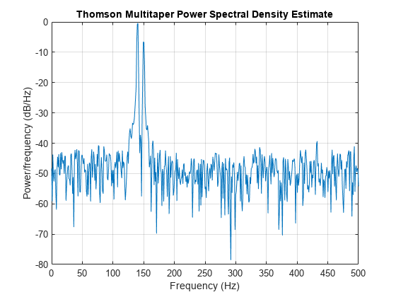
The Signal Processing Toolbox™ function that implements the MTM method is pmtm. Use pmtm to compute the PSD of a signal.
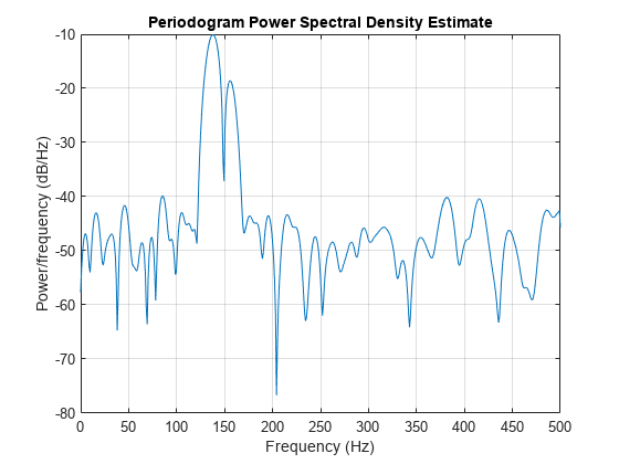
fs = 1000;                % Sampling frequency
t = (0:fs)/fs;            % One second worth of samples
A = [1 2];                % Sinusoid amplitudes
f = [150;140];            % Sinusoid frequencies

xn = A*sin(2*pi*f*t) + 0.1*randn(size(t));
pmtm(xn,4,[],fs)
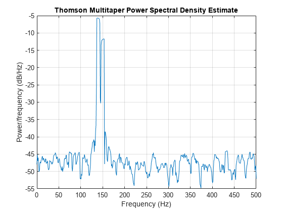
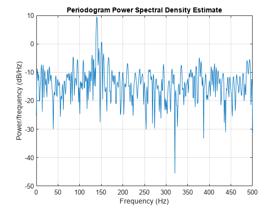
By lowering the time-bandwidth product, you can increase the resolution at the expense of larger variance.
pmtm(xn,1.5,[],fs)
This method is more computationally expensive than Welch's method due to the cost of computing the discrete prolate spheroidal sequences. For long data series (10,000 points or more), it is useful to compute the DPSSs once and save them in a MAT file. dpsssave, dpssload, dpssdir, and dpssclear are provided to keep a database of saved DPSSs in the MAT file dpss.mat.
Cross-Spectral Density Function
The PSD is a special case of the cross spectral density (CPSD) function, defined between two signals x(n) and y(n) as
As is the case for the correlation and covariance sequences, the toolbox estimates the PSD and CPSD because signal lengths are finite.
To estimate the cross-spectral density of two equal length signals x and
y using Welch's method, the cpsd function forms the periodogram as the product of the FFT of
x and the conjugate of the FFT of y. Unlike the
real-valued PSD, the CPSD is a complex function. cpsd handles the sectioning
and windowing of x and y in the same way as the
pwelch function:
Sxy = cpsd(x,y,nwin,noverlap,nfft,fs)
Transfer Function Estimate
One application of Welch's method is nonparametric system identification. Assume that H is a linear, time invariant system, and x(n) and y(n) are the input to and output of H, respectively. Then the power spectrum of x(n) is related to the CPSD of x(n) and y(n) by
An estimate of the transfer function between x(n) and y(n) is
This method estimates both magnitude and phase information. The tfestimate function uses Welch's method to compute the CPSD and power spectrum, and then forms their quotient for the transfer function estimate. Use tfestimate the same way that you use the cpsd function.
Generate a signal consisting of two sinusoids embedded in white Gaussian noise.
rng('default')

fs = 1000;                % Sampling frequency
t = (0:fs)/fs;            % One second worth of samples
A = [1 2];                % Sinusoid amplitudes
f = [150;140];            % Sinusoid frequencies

xn = A*sin(2*pi*f*t) + 0.1*randn(size(t));
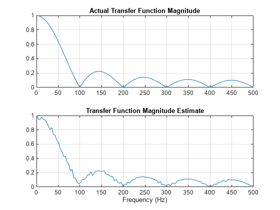
Filter the signal xn with an FIR moving-average filter. Compute the actual magnitude response and the estimated response.
h = ones(1,10)/10;	            % Moving-average filter
yn = filter(h,1,xn);

[HEST,f] = tfestimate(xn,yn,256,128,256,fs);
H = freqz(h,1,f,fs);
Plot the results.
subplot(2,1,1)
plot(f,abs(H))
title('Actual Transfer Function Magnitude')
yl = ylim;
grid
subplot(2,1,2)
plot(f,abs(HEST))
title('Transfer Function Magnitude Estimate')
xlabel('Frequency (Hz)')
ylim(yl)
grid
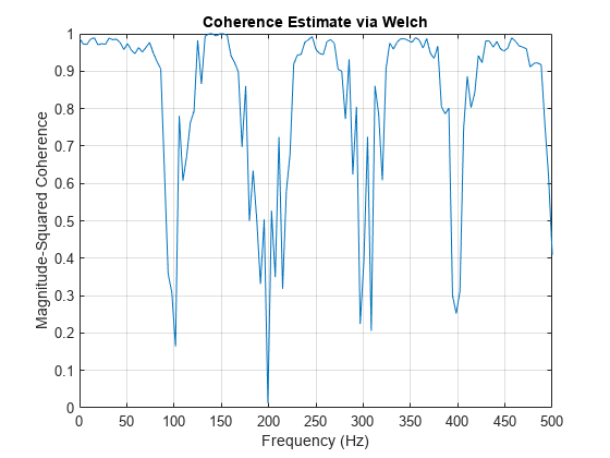
Coherence Function
The magnitude-squared coherence between two signals x(n) and y(n) is
This quotient is a real number between 0 and 1 that measures the correlation between x(n) and y(n) at the frequency .
The mscohere function takes sequences xn and yn, computes their power spectra and CPSD, and returns the quotient of the magnitude squared of the CPSD and the product of the power spectra. Its options and operation are similar to the cpsd and tfestimate functions.
Generate a signal consisting of two sinusoids embedded in white Gaussian noise. The signal is sampled at 1 kHz for 1 second.
rng('default')

fs = 1000;
t = (0:fs)/fs;
A = [1 2];                % Sinusoid amplitudes
f = [150;140];            % Sinusoid frequencies

xn = A*sin(2*pi*f*t) + 0.1*randn(size(t));
Filter the signal xn with an FIR moving-average filter. Compute and plot the coherence function of xn and the filter output yn as a function of frequency.
h = ones(1,10)/10;
yn = filter(h,1,xn);

mscohere(xn,yn,256,128,256,fs)
If the input sequence length, window length, and number of overlapping data points in a window are such that mscohere operates on only a single record, the function returns all ones. This is because the coherence function for linearly dependent data is one.
See Also
Apps
Functions
cpsd|mscohere|periodogram|pmtm|pwelch|tfestimate