Design a Trajectory Planner for a Robotic Manipulator
This example describes one approach to design a grasp and trajectory planner for use with a bin picking system.
In robotics, bin picking involves using a manipulator to retrieve items from a bin. Intelligent bin picking represents an advanced version of this process, offering greater autonomy. Parts are perceived using a camera system, and a planner generates collision-free trajectories that adapt to the scene.
This example shows how to create a trajectory planner component that will work with the bin-picking system. The component is stored as a standalone model that can be called as a referenced model in a harness. The example further uses a simple test harness to validate the planner behavior.
Review the model
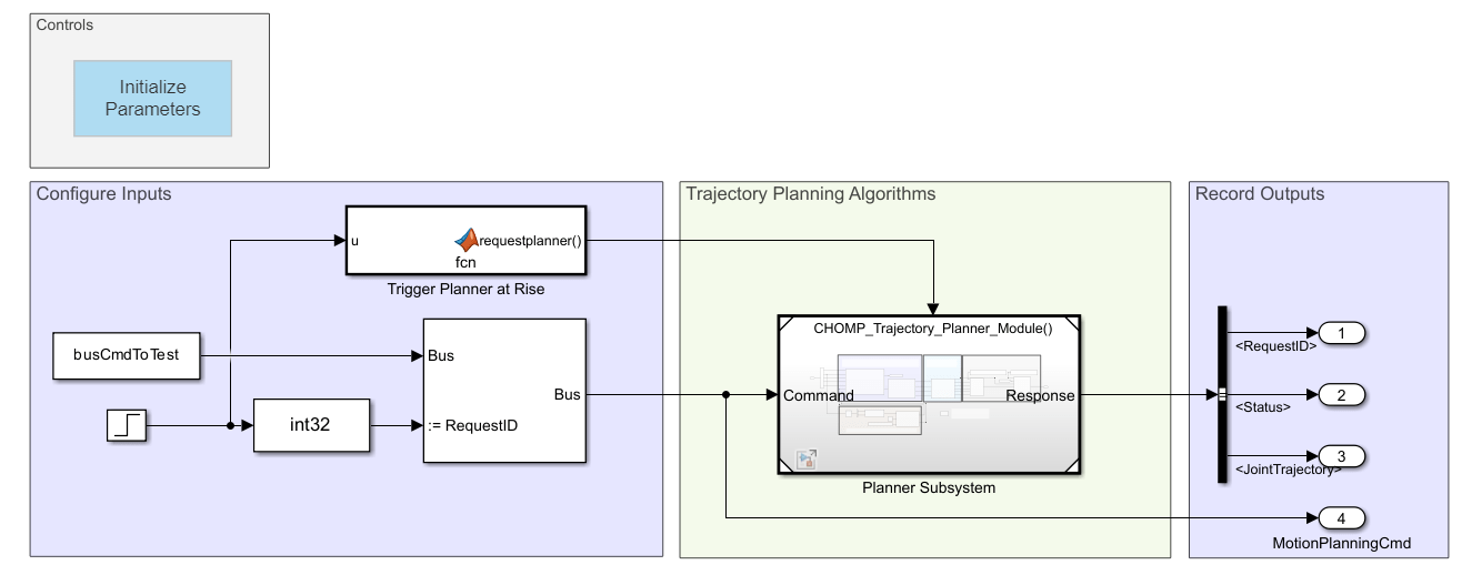
Open the test harness containing the planner model and navigate to the planner subsystem to inspect its contents.
open_system('TrajectoryPlanning_Harness')
open_system('TrajectoryPlanning_Harness/Planner Subsystem')

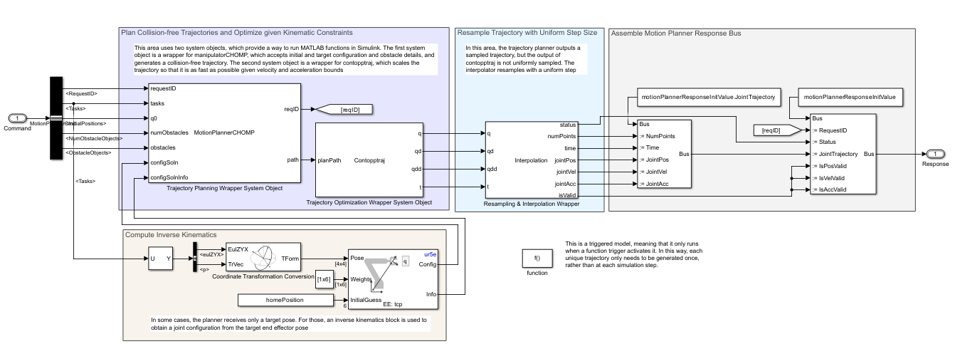
There are several parts to the planner module:
Plan Collision-Free Trajectories and Optimize Kinematic Given Constraints
Scale the generated trajectory so that it is time optimal subject to velocity and acceleration constraints
Interpolate the outcome over a linear spacing
These sections detail these steps:
Compute Inverse Kinematics
In order to compute a collision-free trajectory, the planner must know four things: the start and goal joint configurations, the robot model, and the environment model. While the start configuration is known (it is the robot's current configuration), the goal configuration is often unknown. Instead, the motion planner command may just pass a target pose: a Cartesian-space target for the end effector. When this is the case, the planner first needs to convert the pose to a joint configuration that reaches that pose, which is done using an Inverse Kinematics block.
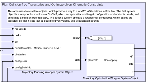
Plan Collision-Free Trajectories and Optimize Given Kinematic Constraints
The bulk of the trajectory planning happens in two blocks within this area. Both blocks are system objects, which is a type of file similar to a MATLAB Function block that can be used to run MATLAB code in Simulink. Unlike a MATLAB function block, however, the system object can be executed in code generation and interpreted modes, allowing more flexible execution.

This routine uses two system objects:
MotionPlannerCHOMP— This is a wrapper for amanipulatorCHOMPobject. The system object accepts the start and goal configuration and details of the obstacles. It also takes the robot and static environment details as parameters. Internally, the bulk of the computation is handled by the helper file,exampleHelperCHOMPMotionPlanner, which creates and executes the planner. For performance, this code is mexed and the mexed code is ultimately called in lieu of the original MATLAB in the system object. You can take a look at the system object or motion planner code with the following commands:
edit('MotionPlannerCHOMP.m'); % System object
edit('exampleHelperCHOMPMotionPlanner.m'); % Planner creation & execution within the system object
Contopptraj— This is a system object wrapper for thecontopptrajfunction, a TOPP-RA solver. This function takes a known trajectory and re-parameterizes it so the trajectory is traversed as possible while respecting some provided velocity and acceleration limits. The result is a time-optimal trajectory. You can inspect this code with the this command.
edit('Contopptraj.m')
These two blocks in sequence return a sampled collision-free trajectory that is time-optimal given kinematic constraints. However, while contopptraj returns a complete trajectory, it is not uniformly sampled.
As noted above, the planner code relies on a mexed version for performance, which is attached. You can generate this code yourself with the following command:
generateMEXforPlanner
Resample Trajectory with Uniform Step Size
A system object containing an interpolator is used to take the non-uniformly-sampled trajectory and re-sample it using a fine-grained, uniform sample. This complete trajectory can then be output to a target controller for execution.
Lastly, the outputs are reassembled into an output bus format. This is detailed in the interfaces section below.
Bus Overview
The model accepts a bus of robot commands, indicating the nature of the trajectory planning task, and motion planning response bus, which contains the generated trajectory and some associated solution data. The buses have the structure described below.
You could choose to build a completely different interface, but it would be necessary to use the same buses to communicate. Note that the buses have many fields, but only a few are absolutely necessary.
Robot Command Bus
The input type is a bus of robot commands. The structure can be seen by looking at the initialization struct:
busCmdToTest = motionPlannerCmdInitValue;
There are a few key parameters:
The
RequestIDis a number that is positive when a task is sent. In this module, the request ID is passed through as long as the planner executes. In the parent task scheduler, the request ID is used to verify when a task has been completed by comparing it to the ID of the commanded task.The
Tasksarray is a structure that details each specific task. This is where the meat of the planning instruction is provided. Two supplementary properties describe these tasks:MaxNumTasksindicates the upper bound on the number of tasks per command, andNumTasksindicates the number of provided tasks this command. However, in this module, these are unused, and only the first task is queried. This array is further detailed below.The
ObstacleObjectsproperty allows a user to pass in obstacles beside the static environment. The number of provided obstacles is given byNumObstacleObjects, and the maximum is specified inMaxNumObstacleObjects. This parameter is optional, and typically unused when the obstacles don't significantly obstruct the robot's workspace.The
InitialPositionsproperty indicates the start configuration for a given trajectory plan.The
MaxIterationsproperty defines the maximum number of iterations for the planner.The
SampleTimeproperty indicates the sample time of the planned trajectory.
Variable-Size Commands
Note that Tasks and ObstacleObjects are initialized to 20-by-1 structures, but the number of tasks and provided obstacles can vary. To accommodate deployment requirements, these arrays are provided as a fixed size corresponding to a set maximum number. For each array, the associated parameter NumTasks or NumObstacleObjects defines the number of items for the planner to actually query.
Tasks Array
Each task is stored in a task array, with the following format:
busCmdToTest.Tasks(1)
ans = struct with fields:
                    Name: [0 0 0 0 0 0 0 0 0 0 0 0 0 0 0 0 0 0 0 0 0 0 0 0 0 0 0 0 0 0 0 0 0 0 0 0 0 0 0 0 0 0 0 0 0 0 0 0 0 0 0 0 0 0 0 0 0 0 0 0 0 0 0 0 0 0 0 0 0 0 0 0 0 0 0 0 0 0 0 0 0 0 0 0 0 0 0 0 0 0 0 0 0 0 0 0 0 0 0 0 0 0 0 0 0 … ] (1×256 uint8)
                    Type: [0 0 0 0 0 0 0 0 0 0 0 0 0 0 0 0 0 0 0 0 0 0 0 0 0 0 0 0 0 0 0 0 0 0 0 0 0 0 0 0 0 0 0 0 0 0 0 0 0 0 0 0 0 0 0 0 0 0 0 0 0 0 0 0 0 0 0 0 0 0 0 0 0 0 0 0 0 0 0 0 0 0 0 0 0 0 0 0 0 0 0 0 0 0 0 0 0 0 0 0 0 0 0 0 0 … ] (1×256 uint8)
               FrameName: [0 0 0 0 0 0 0 0 0 0 0 0 0 0 0 0 0 0 0 0 0 0 0 0 0 0 0 0 0 0 0 0 0 0 0 0 0 0 0 0 0 0 0 0 0 0 0 0 0 0 0 0 0 0 0 0 0 0 0 0 0 0 0 0 0 0 0 0 0 0 0 0 0 0 0 0 0 0 0 0 0 0 0 0 0 0 0 0 0 0 0 0 0 0 0 0 0 0 0 0 0 0 0 0 0 … ] (1×256 uint8)
                       p: [3×1 double]
                  eulZYX: [3×1 double]
                       q: [6×1 double]
               MaxLinVel: 0
               MaxAngVel: 0
                  MaxVel: 0
                  Weight: 0
             MaxLinError: 0
             MaxAngError: 0
           MaxJointError: 0
    ConvergenceSpeedGain: 0
            SecurityDist: 0
           InfluenceDist: 0
This array has several important fields:
The
Name,Type, andFrameNameproperties are used to track the task details. They are stored as fixed-lengthuint8but can be converted to character by using thecharfunction. For example, by default, the name field is unassigned, returning all spaces:
char(busCmdToTest.Tasks(1).Name)
ans =
'                                                                                                                                                                                                                                                                '
The
pandeulZYXproperties specify the target position and orientation (in Euler zyx-sequence) of the end effector, respectively. These two together define the target pose of the end effector for a given plan. When these values are provided, the planner subsequently relies on inverse kinematics to translate end-effector pose to a target configuration.The
qproperty can be used to specify a target configuration. However, it is unused by the current planner.
The remaining parameters are optional and may be used to provide constraints to the planner.
ObstacleObjects Array
The obstacle objects array provides another way for the user to provide primitive obstacles of type collisionBox. This is unused in this test harness. To understand the usage more closely, open the following helper, which builds the environment from the structured input:
edit('exampleHelperGenerateCollisionEnvironmentInPlanner.m')
Unused Properties in Input Buses
The buses provided as input have been designed for use with several different subsystems. That means that many of the properties may be left unused. For example, this planner module makes several simplifications:
Only the first task is queried. The other 19 tasks are ignored.
The planner only looks at target poses. Any target configurations passed in are ignored.
Many of the planner parameters, such as maximum linear velocity, are not relevant to this planner.
Other planner modules could make use of these inputs. Using this harness, you could similarly verify.
Motion Planner Response Bus
After the trajectory has been planned, they must be output. First the trajectories are assembled into a structure that provides the complete, sampled trajectory:
motionPlannerResponseInitValue.JointTrajectory
ans = struct with fields:
       NumPoints: 0
    MaxNumPoints: 30000
            Time: [0 0 0 0 0 0 0 0 0 0 0 0 0 0 0 0 0 0 0 0 0 0 0 0 0 0 0 0 0 0 0 0 0 0 0 0 0 0 0 0 0 0 0 0 0 0 0 0 0 0 0 0 0 0 0 0 0 0 0 0 0 0 0 0 0 0 0 0 0 0 0 0 0 0 0 0 0 0 0 0 0 0 0 0 0 0 0 0 0 0 0 0 0 0 0 0 0 0 0 0 0 0 0 0 0 0 0 0 … ] (1×30000 double)
        JointPos: [6×30000 double]
        JointVel: [6×30000 double]
        JointAcc: [6×30000 double]
        JointTau: [6×30000 double]
Here the MaxNumPoints again indicates the upper bound on trajectory size. All properties are important:
The
NumPointsproperty sets the number of points actually used by the trajectory. For example, for a 5 second trajectory sampled at 1000 Hz, only the first 5000 indices will be used.The
Timeproperty indicates the sampled trajectory time. This is initialized to a 1-by-MaxNumPointsmatrix of zeros, and the planned time occupies the firstNumPointselements.,The
JointPos,JointVel,JointAcc, andJointTaucontain the joint configuration, velocity, acceleration, and jerk, respectively. These are initialized to N-by-MaxNumPointsmatrices of zeros, but the planned trajectory occupy the first N-by-NumPointsindices. Here N is the number of non-moving joints in the robot. For the UR5e cobot, N is equal to 6.
Finally, the JointTrajectory bus is inserted into the motion planner response bus. This bus is mostly a set of flags:
motionPlannerResponseInitValue
motionPlannerResponseInitValue = struct with fields:
          RequestID: -1
             Status: -1
    JointTrajectory: [1×1 struct]
         IsPosValid: -1
         IsVelValid: -1
         IsAccValid: -1
         IsTauValid: -1
The bus has the following properties:
RequestIDis the request ID of the task. Typically this is used by the calling scheduler to verify that the task that was requested was also the one that was executed.The
Statusis 1 when the plan is complete and an interpolated trajectory has been provided.The
JointTrajectoryproperty contains the previously specified planned trajectory.The last four properties are set to 1 to indicate the planned joint position, velocity, acceleration, and jerk are valid, respectively
Validate Controller with Simple Planning Tasks
We can validate the motion planning module using a simple test harness. The harness is designed to test the two main functionalities that this block must achieve:
Given a current joint configuration and a reachable target pose, compute a collision-free trajectory between the two poses
Given a current joint configuration and an object at a specified pose, compute a collision-free trajectory that positions the robot in a suitable grasping pose
Initialize Inputs to the Test Harness
The provided harness does this using two separate subsystems that alternate execution. Start by loading the system.
open_system('TrajectoryPlanning_Harness');
Next, initialize the parameters and assign meaningful values to the input bus:
busCmdToTest = motionPlannerCmdInitValue;
busCmdToTest.RequestID = int32(1);
busCmdToTest.NumTasks = uint32(4);
busCmdToTest.InitialPositions = homePosition(:);
busCmdToTest.MaxIterations = uint32(300);
busCmdToTest.SampleTime = 0.2;
busCmdToTest.NumObstacleObjects = uint32(2); % This value should be nonzero to ensure the planner runs
The specific functionalities are defined in the task structure. Two tasks are created. First, a pick task is defined:
pickTask = busCmdToTest.Tasks(1);
pickTask.Name(1:length('TooltipTaskSE3')) = uint8('TooltipTaskSE3');
pickTask.Type(1:length('Pick')) = uint8('Pick');
pickTask.FrameName(1:length('Bellow')) = uint8('Bellow');
pickTask.p = [0.485; -0.0032; -0.0368];
pickTask.eulZYX = [1.2041; pi; 0];
pickTask.MaxLinVel = 0.1;
pickTask.MaxAngVel = 0.4;
pickTask.Weight = 1;
pickTask.MaxLinError = 0.01;
pickTask.MaxAngError = 0.0349;
Next, a place task is created by copying the picking task and making some minor edits to the goal configuration:
placeTask = pickTask;
placeTask.Type(1:length('Place')) = uint8('Place');
placeTask.p = [0.1 0.6 0.07]';
placeTask.eulZYX = [1.2041; pi; 0];
Plan Paths for Each Test Task Using the Test Harness
Run the test harness for each task, storing the outputs:
busCmdToTest.Tasks(1) = pickTask;
pickout = sim('TrajectoryPlanning_Harness.slx');

busCmdToTest.Tasks(1) = placeTask;
busCmdToTest.InitialPositions = [-0.2850 -1.5035 2.0352 -2.1025 -1.5708 0.0817]';
placeout = sim('TrajectoryPlanning_Harness.slx');
Analyze and Validate Outcomes
To validate the simulation, we will visualize the results in MATLAB. This makes use of two helper functions defined at the bottom of this script. The helpers simply convert the stored model outputs into meaningful data that can be visualized.
% Create the environment in which the robot is to be visualized
task_obst = exampleHelperGenerateCollisionEnvironmentInPlanner(uint8(targetEnv),binLength, binWidth, binHeight, binCenterPosition, binRotation, ...
    1, zeros(1,4));
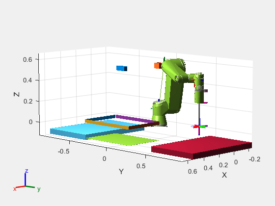
Visualize Picking Task Outcomes
[pick_status, pick_task_traj, picktargetRegion] = helperReadModelData(pickout);

figure;
title('Animate the Picking Task');
show(ur5e, pick_task_traj(:,1)');
hold on
show(picktargetRegion)
showCollisionArray(task_obst);
axis equal
Animate the complete trajectory
rc = rateControl(25);
for i = 1:size(pick_task_traj,2)
    drawnow;
    show(ur5e, pick_task_traj(:,i)', FastUpdate=true, PreservePlot=false);
    waitfor(rc);
end

Visualize Placing Task Outcomes
[task_status, place_task_traj, placetargetRegion] = helperReadModelData(placeout);

figure;
title('Animate the Placing Task');
show(ur5e, place_task_traj(:,1)',Collisions="on");
hold on
show(placetargetRegion)
showCollisionArray(task_obst);
axis equal
rc = rateControl(25);
for i = 1:size(place_task_traj,2)
    drawnow;
    show(ur5e, place_task_traj(:,i)', FastUpdate=true, PreservePlot=false,Collisions="on");
    waitfor(rc);
end

Helper Functions
function [task_status, task_traj, targetRegion] = helperReadModelData(out)

% Read input data
tasks = out.yout{4}.Values.Tasks(1);
tgtPoses = [tasks.p.Data; tasks.eulZYX.Data];

% Read output data
reqs = out.yout{1}.Values.Data;
status = out.yout{2}.Values.Data;
trajs = out.yout{3}.Values;

% Determine the intervals where the request changes and sort into indices
reqchanges = find(diff(reqs)~=0); %Better than unique because duplicates are not filtered out
reqidx = [[1; reqchanges+1] [reqchanges; numel(reqs)]];

% Get the data corresponding to the first req
taskIDX = 1;
taskind = reqidx(taskIDX+1,:);

% Get the task status and trajectory corresponding to the task
task_status = status(taskind(1):taskind(2));
task_trajsize = trajs.NumPoints.Data(taskind(1));
task_traj = trajs.JointPos.Data(:,1:task_trajsize,taskind(1));

% Create a target region to indicate where the robot trajectory is supposed
% to end. Since this planner treats the target orientation as Z only, the
% valid region is set as a rotation about Z.
targetPoseVec = tgtPoses(:,:,taskind(1));
targetPoseTF = [axang2rotm([0 0 1 targetPoseVec(6)]) targetPoseVec(1:3); 0 0 0 1];
targetRegion = workspaceGoalRegion('tcp',ReferencePose=targetPoseTF);
targetRegion.Bounds(4,:) = [-pi pi]; % Not strictly required but shows that with suction, this is really a region and not a specific target

end
See Also
manipulatorCHOMP | contopptraj | Inverse
Kinematics