AUTOSAR Client-Server Communication
In Simulink®, you can model AUTOSAR client-server communication for simulation and code generation. For information about the Simulink blocks you use and the high-level workflow, see Client-Server Interface.
To model AUTOSAR servers and clients, you can do either or both of the following:
Import AUTOSAR servers and clients from ARXML code into a model.
Configure AUTOSAR servers and clients from Simulink blocks.
AUTOSAR Server Model Configuration and Code Generation
This topic explores an example model,
mControllerWithInterface_server, that models an AUTOSAR
server.
Contents of the Server Model
Open the relevant supporting files by entering the following commands at the MATLAB® command line:
openExample("mControllerWithInterface_server.slx")The example model provides two Simulink Function blocks,
doOverride and readData.
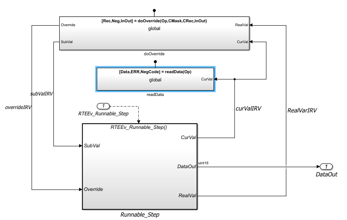
In the example model, the contents of the Simulink Function block
readData implements readData server
function.
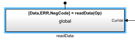
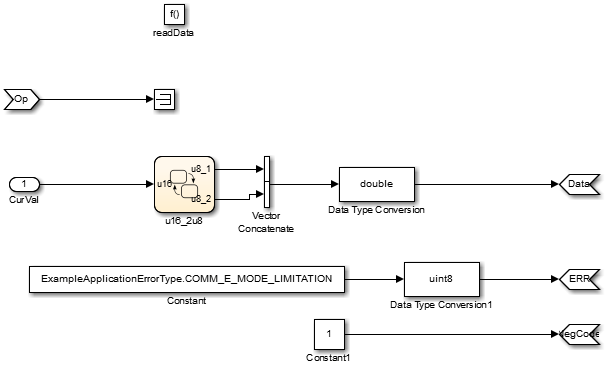
The content of the Simulink Function block include blocks that
implement the readData server function:
Trigger block
readData, representing a trigger port for the server function. Treat as Simulink function is selected. Function name is set toreadData. Function visibility is set toglobal.Argument Inport block
Opand Argument Outport blocksData,ERR, andNegCode, correspond to the function prototype[Data,ERR,NegCode] = readData(Op).A Stateflow chart handling the data conversion of input argument
CurVal, the output of which is fed into a Vector Concatenate block, a Data Type Conversion block which changes the data type to a double. Which then feeds theDataArgument Outport block.A Constant block represents the value of an application error defined for the server function.
The value of Op passed by the caller is ignored. In a
real-world application, the algorithm could perform a more complex manipulation, for
example, selecting an execution path based on the passed value of
Op, producing output data required by the application, and
checking for error conditions.
Note
When configuring server function arguments, you must specify signal data type, port dimensions, and signal type on the Signal Attributes tab of the inport and outport blocks. The AUTOSAR configuration fails validation if signal attributes are absent for server function arguments.
AUTOSAR Server Properties
In the AUTOSAR Dictionary, the required elements to configure an AUTOSAR server are:
AUTOSAR client-server (C-S) interface in the AUTOSAR Dictionary.
One or more AUTOSAR operations for which the interface handles client requests.
AUTOSAR server port to receive client requests for a server operation.
For each server operation, an AUTOSAR server runnable to execute client requests.
In the model, open the AUTOSAR Dictionary. To view AUTOSAR client-server interfaces in the model, go to the C-S Interfaces view. The example model already contains a client-server interface.
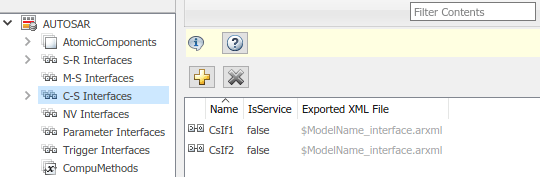
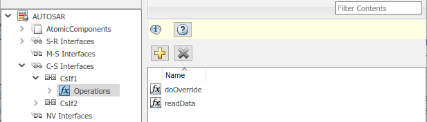
To view operations for CsIf1 interface expand C-S
Interfaces, and then expand CsIf1 and select
Operations. The example model already contains AUTOSAR
server operations named doOverride and
readData.
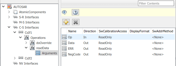
To examine the arguments listed for the AUTOSAR server operation
readData. Expand Operations, then expand
operation readData, and select Arguments.
The listed arguments correspond to the Simulink server function prototype [Data,ERR,NegCode] =
readData(Op).
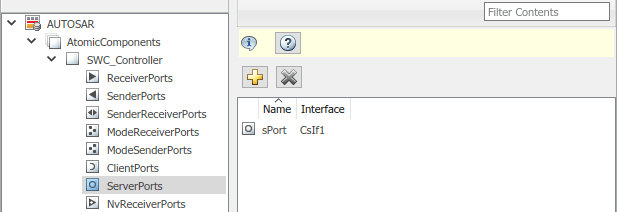
To view AUTOSAR server ports in the model navigate to the
ServerPorts view. Expand
AtomicComponents, expand
SWC_Controller, and select
ServerPorts. The example model contains an AUTOSAR server port
named sPort typed by client-server interface
CsIf1.
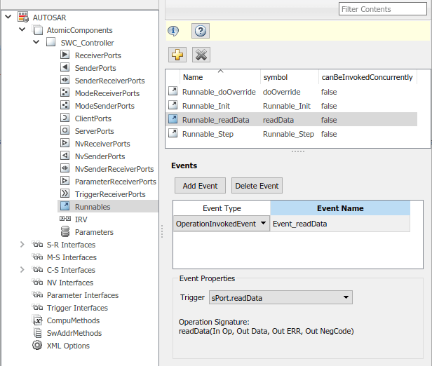
To model client-server communication, each AUTOSAR server operation must be mapped
to an AUTOSAR server runnable that implements the operation. The example model
contains a server runnable for readData, named
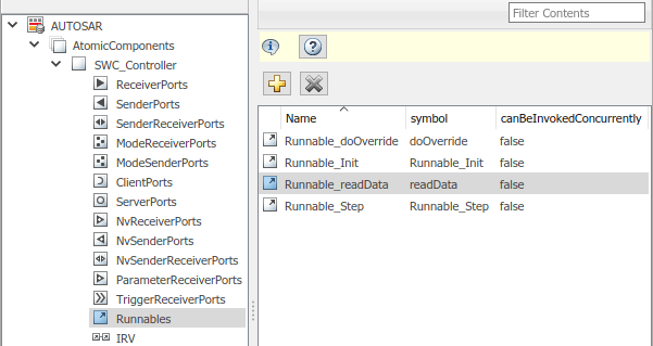
Runnable_readData. To view available AUTOSAR runnables in the
model, select Runnables. Select
Runnable_readData, the Events pane
opens. Runnable_readData has an event
Event_readData of type
OperationInvokedEvent, meaning that when the operation of the
server is invoked it triggers the runnable to execute. Select
Event_readData to configure its properties. In the example
model, the event is already configured to trigger when operation
sPort.readData is invoked.
Similarly, select Runnable_doOverride to view its events and
event properties, it has an OperationInvokedEvent,
Event_doOverride, which is triggered by
sPort.doOverride. Select Runnable_Step
to view its events and event properties. Since Runnable_Step is a
periodic runnable it is triggered by a TimingEvent called
Event_RTEEv_Runnable_Step. For more information about
modeling runnables, see Multiple Runnables Configured as Periodic-Rate Runnable and Asynchronous Function-Call Runnable.
Simulink Function to AUTOSAR Server Runnable Mapping
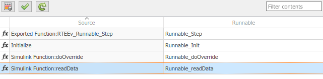
Return to the model and open the Code Mappings editor. In the
Functions tab, the Simulink Function readData is mapped to AUTOSAR server
runnable Runnable_readData.
Validate Code Mappings
To determine code generation readiness, validate the AUTOSAR component mapping
configuration, click the Validate button
![]() in the Code Mappings editor.
in the Code Mappings editor.
Generate Code and Export ARXML
Generate C code and export ARXML files for the model. Examine the generated code.
The code generator produces a code generation report showing the generated
Model files and Interface files. The
model files include file mControllerWithInterface_server.c. C
code describing functions readData and
overrideData are generated.
By default, the software exports modular ARXML files. To export ARXML as a single
file, set XML option Exported XML file packaging to
Single file.
This example exports modular ARXML files:
mControllerWithInterface_server_component.arxmlmControllerWithInterface_server_datatype.arxmlmControllerWithInterface_server_implementation.arxmlmControllerWithInterface_server_interface.arxmlmControllerWithInterface_server_timing.arxml
Notably, AUTOSAR server port sPort that was configured in this
example is generated in the
mControllerWithInterface_server_component.arxml file. It
contains communication specifications that reference the operations defined in the
model.
...
<SHORT-NAME>sPort</SHORT-NAME>
<PROVIDED-COM-SPECS>
<SERVER-COM-SPEC>
<OPERATION-REF DEST="CLIENT-SERVER-OPERATION">/ControllerWithInterface_ar_pkg/ControllerWithInterface_ar_if/CsIf1/doOverride</OPERATION-REF>
<QUEUE-LENGTH>1</QUEUE-LENGTH>
</SERVER-COM-SPEC>
<SERVER-COM-SPEC>
<OPERATION-REF DEST="CLIENT-SERVER-OPERATION">/ControllerWithInterface_ar_pkg/ControllerWithInterface_ar_if/CsIf1/readData</OPERATION-REF>
<QUEUE-LENGTH>1</QUEUE-LENGTH>
</SERVER-COM-SPEC>
</PROVIDED-COM-SPECS>
<PROVIDED-INTERFACE-TREF DEST="CLIENT-SERVER-INTERFACE">/ControllerWithInterface_ar_pkg/ControllerWithInterface_ar_if/CsIf1</PROVIDED-INTERFACE-TREF>
</P-PORT-PROTOTYPE>
</PORTS>
...For more information about generated C code from AUTOSAR models, see AUTOSAR Classic Component Code Generation Files.
AUTOSAR Client Model Configuration and Code Generation
This topic explores an example model,
mControllerWithInterface_client, of an AUTOSAR client. This model
calls the server operation modeled in
mControllerWithInterface_server.slx.
Contents of the Model
Open the example model
mControllerWithInterface_client.slx.
openExample("mControllerWithInterface_client");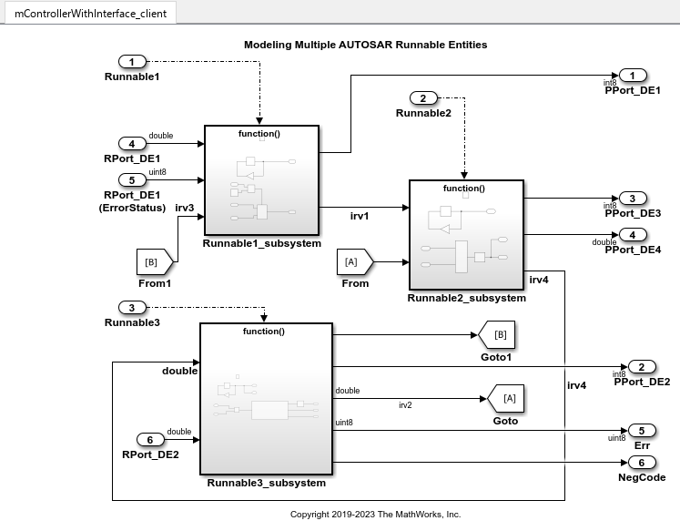
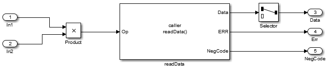
The example model provides a Function Caller block named
readData located inside the
Runnable3_Subsystem. The readData
Function Caller block is connected to inports, outports, and signal
lines matching the function argument data types and dimensions of the
Simulink Function block defined in the AUTOSAR server example,
AUTOSAR Server Model Configuration and Code Generation.
Note
Whenever you add or change a Function Caller block in an
AUTOSAR model, update function callers in the AUTOSAR configuration. Open the
Code Mappings editor. In the dialog box, click the Update
button ![]() . This action loads or updates Simulink data transfers, function callers, and numeric types in your model.
After updating, the function caller you added appears in the Function
Callers tab of the Code Mappings editor.
. This action loads or updates Simulink data transfers, function callers, and numeric types in your model.
After updating, the function caller you added appears in the Function
Callers tab of the Code Mappings editor.
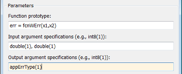
The Function Caller block parameters include function prototype and argument specification fields. The Function Caller block parameters in the client model must match the server function definition in the server model.
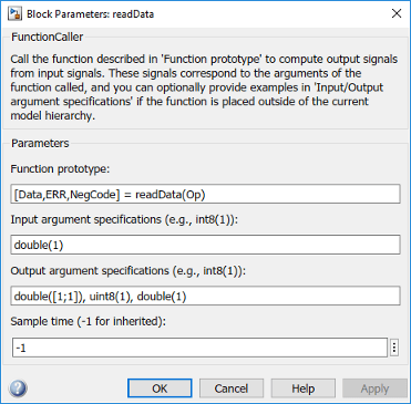
For reference, here is the readData function from the server
example to which the Function Caller block in the client model
corresponds.
If you have System Composer™ you can graphically associate a client and server by using an AUTOSAR architecture model. For more information about AUTOSAR clients and servers in architecture models, see Assemble and Simulate AUTOSAR Software Components in Architecture Model.
AUTOSAR Client Properties
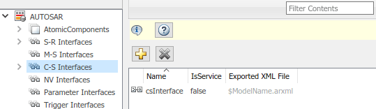
Open the AUTOSAR Dictionary. To view AUTOSAR C-S interfaces in the model, navigate
to the C-S Interfaces view. The example model already contains
a client-server interface named CsIf1.
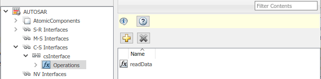
Expand C-S Interfaces, expand CsIf1. To
view operations for the interface, select Operations. The
example model already contains an AUTOSAR operation named
readData.
View the AUTOSAR operation arguments. Expand Operations,
expand the operation readData, and select
Arguments. Arguments NegCode,
ERR, Data, Op are
defined along with the direction of the ports, either In,
Out, or Error. The AUTOSAR operation and
arguments match the Function Caller block prototype
[Data,ERR,NegCode] = readData(Op) in the model.
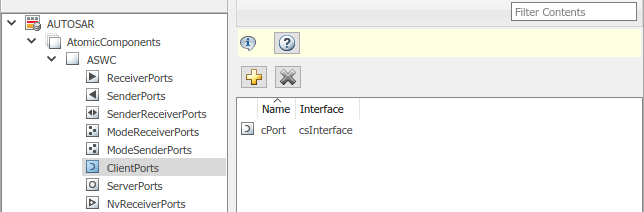
To view AUTOSAR client ports in the model, navigate to the
ClientPorts view. Expand
AtomicComponents, expand ASWC, and
select ClientPorts. The example model already contains an
AUTOSAR client port named cPort typed by client-server interface
CsIf1.
Simulink Function Caller to AUTOSAR Client Port Mapping
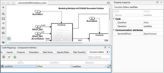
Return to the model and open the Code Mappings editor. In the Function
Callers tab, the Simulink client function readData is mapped to AUTOSAR
ClientPort
cPort, specifically it is mapped to the client port operation
readData.

In addition to mapping Simulink function callers to AUTOSAR client port operations, you can set the communication style of the server call point as either synchronous (blocking behavior) or asynchronous (nonblocking behavior). When the caller behavior is set to asynchronous, the software utilizes a polling approach, meaning that the runnable invokes the operation and checks if the server results are ready every time that the runnable runs. At the same time, the client output maintains the last value it received from the server. When the server results are ready, the client output is updated and the server is invoked again. Allowing the client to be unblocked by the server reduces overhead for complex processes and increases run-time efficiency of the model.
To view or change the ServerCallPoint setting, open the
Property Inspector and select Function Caller readData in the
Code Mappings editor. In the Property Inspector, expand Communication
attributes. Setting ServerCallPoint determines
the calling behavior of the client, it can be set to either
Synchronous (blocking) or Asynchronous
(non-blocking). In the example model, client port cPort has
communication attribute ServerCallPoint set to
Asynchronous.
Validate Code Mappings
To determine code generation readiness, validate the AUTOSAR component mapping
configuration, click the Validate button
![]() in the Code Mappings editor.
in the Code Mappings editor.
Optional: Simulate Client and Server with Simulink Test Harness
While simulation is not required for this example, if you want to simulate the
function invocation at this point you can create a test harness for the client
model. Alternatively, combine the
mControllerWithInterface_server.slx model and the
mControllerWithInterface_client.slx as software components in
the same architecture model by using System Composer for more information about this workflow, see Assemble and Simulate AUTOSAR Software Components in Architecture Model.
Note
Function callers, regardless of the setting of their communication attribute ServerCallPoint, are simulated synchronously.
To simulate the AUTOSAR client model in this example, create a Simulink
Test™ harness. On the Modeling toolstrip select the Simulink
Test app ![]() in the Apps > Model Verification, Validation, and Test section. On the Simulink
Test toolstrip, select Add Test Harness to create a
test harness for the model. The Create Test Harness dialog box
opens. Select the path to save the harness model in the Harness
path and enable Save test harnesses externally.
Click OK. The test harness for the client model opens.
in the Apps > Model Verification, Validation, and Test section. On the Simulink
Test toolstrip, select Add Test Harness to create a
test harness for the model. The Create Test Harness dialog box
opens. Select the path to save the harness model in the Harness
path and enable Save test harnesses externally.
Click OK. The test harness for the client model opens.
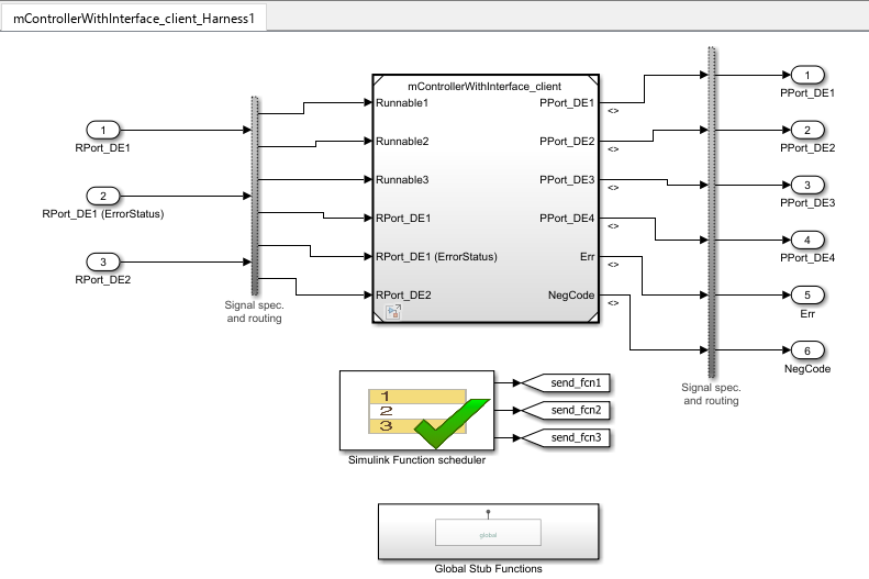
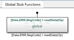
The test harness creates a Global Stub Functions subsystem,
which provides stub definition of function readData. It also
creates a Simulink Function scheduler to automatically schedule the runnables
defined in the client model.
The Simulink Test harness is not suitable for AUTOSAR code generation and exists purely for simulation and verification purposes.
Generate and Inspect Code and Export ARXML for Asynchronous Client Ports
After validating code mappings, generate and inspect C code and export ARXML files for the model. The code generator produces a code generation report showing the generated Model files and Interface files. For information about generated C code from AUTOSAR models, see AUTOSAR Classic Component Code Generation Files.
For AUTOSAR client ports with communication attribute
ServerCallPoint set to Asynchronous the
generated code contains two calls: Rte_Call to invoke the server
and Rte_Result to get the server results. The
Rte_Call contains the list of IN and
INOUT arguments, while the Rte_Result
contains the list of INOUT and OUT
arguments.
...
/* Model step function for TID3 */
void Runnable3(void)                   /* Explicit Task: Runnable3 */
{
  sint8 Delay;
  sint8 rtb_Gain;
  sint8 rtb_OutportBufferForTicToc;
...
  /* FunctionCaller: '<S3>/readData' incorporates:
   *  DataTransferBlock generated from: '<Root>/Runnable2_subsystem'
   *  Inport: '<Root>/RPort_DE2'
   *  Product: '<S3>/Product'
   */
  Rte_Call_cPort_readData(Rte_IrvIRead_Runnable3_IRV4() *
    Rte_IRead_Runnable3_RPort_DE2());
  Rte_Result_cPort_readData(rtARID_DEF.readData_o1, &rtARID_DEF.readData_o2,
    &rtARID_DEF.readData_o3);
...
  /* Outport: '<Root>/PPort_DE2' */
  Rte_IWrite_Runnable3_PPort_DE2(rtb_OutportBufferForTicToc);

  /* Outport: '<Root>/Err' */
  Rte_IWrite_Runnable3_PPort_Err(rtARID_DEF.readData_o2);

  /* Outport: '<Root>/NegCode' */
  Rte_IWrite_Runnable3_PPort_NegCode(rtARID_DEF.readData_o3);
}
...
In the exported ARXML files, the
ASYNCHRONOUS-SERVER-CALL-RESULT-POINT indicates which
runnable processes the result, in this case Runnable3. The
ASYNCHRONOUS-SERVER-CALL-RESULT-POINT references the
ASYNCHRONOUS-SERVER-CALL-POINT.
...
<ASYNCHRONOUS-SERVER-CALL-RESULT-POINTS>
    <ASYNCHRONOUS-SERVER-CALL-RESULT-POINT UUID="...">
        <SHORT-NAME>SCR_cPort_readData</SHORT-NAME>
        <ASYNCHRONOUS-SERVER-CALL-POINT-REF...
DEST="ASYNCHRONOUS-SERVER-CALL-POINT">/pkg/swc/ASWC/IB/Runnable3/SC_cPort_readData</ASYNCHRONOUS-SERVER-CALL-POINT-REF>
    </ASYNCHRONOUS-SERVER-CALL-RESULT-POINT>
</ASYNCHRONOUS-SERVER-CALL-RESULT-POINTS>
...
When you import ARXML files with descriptions of asynchronous client ports
Simulink requires that the
ASYNCHRONOUS-SERVER-CALL-RESULT-POINT and
ASYNCHRONOUS-SERVER-CALL-POINT be defined together in the
same runnable description. Otherwise, server call points are set to
Synchronous after import and model creation.
Generate and Inspect Code and Export ARXML for Synchronous Client Ports
After validating code mappings, generate and inspect C code and export ARXML files for the model. The code generator produces a code generation report showing the generated Model files and Interface files. For information about generated C code from AUTOSAR models, see AUTOSAR Classic Component Code Generation Files.
For function callers mapped to AUTOSAR client ports with communication attribute
ServerCallPoint set to Synchronous the
RTE call to function readData of AUTOSAR client port
cPort handles results of the server as input arguments. For
example, Runnable3 in the following code contains function
Rte_Call_cPort_readData which requires server results as
input arguments in order to execute, specifically:
rtbARID_DEF.readData.o1, rtb_readData_o2,
and rtb_readData_o3.
...
/* Model step function for TID3 */
void Runnable3(void)                   /* Explicit Task: Runnable3 */
{
  float64 rtb_readData_o3;
  sint8 Delay;
  sint8 rtb_OutportBufferForTicToc;
  uint8 rtb_readData_o2;
...
  /* FunctionCaller: '<S3>/readData' incorporates:
   *  DataTransferBlock generated from: '<Root>/Runnable2_subsystem'
   *  Inport: '<Root>/RPort_DE2'
   *  Product: '<S3>/Product'
   */
  Rte_Call_cPort_readData(Rte_IrvIRead_Runnable3_IRV4() *
    Rte_IRead_Runnable3_RPort_DE2(), rtARID_DEF.readData_o1, &rtb_readData_o2,
    &rtb_readData_o3);
...
  /* Outport: '<Root>/PPort_DE2' */
  Rte_IWrite_Runnable3_PPort_DE2(rtb_OutportBufferForTicToc);

  /* Outport: '<Root>/Err' */
  Rte_IWrite_Runnable3_PPort_Err(rtb_readData_o2);

  /* Outport: '<Root>/NegCode' */
  Rte_IWrite_Runnable3_PPort_NegCode(rtb_readData_o3);
}
...
In the exported ARXML files, function readData on the client
port has a synchronous server call point, and includes the AUTOSAR client-server
interface and operation.
...
<SERVER-CALL-POINTS>
  <SYNCHRONOUS-SERVER-CALL-POINT UUID="...">
    <SHORT-NAME>SC_cPort_readData</SHORT-NAME>
    <OPERATION-IREF>
      <CONTEXT-R-PORT-REF DEST="R-PORT-PROTOTYPE">/pkg/swc/ASWC/cPort</CONTEXT-R-PORT-REF>
      <TARGET-REQUIRED-OPERATION-REF DEST="CLIENT-SERVER-OPERATION">/pkg/if/CsIf1/readData</TARGET-REQUIRED-OPERATION-REF>
    </OPERATION-IREF>
    <TIMEOUT>1.0E-06</TIMEOUT>
  </SYNCHRONOUS-SERVER-CALL-POINT>
</SERVER-CALL-POINTS>
...
For more information about generated ARXML files and their contents, see Configure AUTOSAR Code Generation.
Configure AUTOSAR Client-Server Error Handling
AUTOSAR defines an application error status mechanism for client-server error handling. An AUTOSAR server returns error status, with a value matching a predefined possible error. An AUTOSAR client receives and responds to the error status. An AUTOSAR software component that follows client-server error handling guidelines potentially provides error status to AUTOSAR Basic Software, such as a Diagnostic Event Manager (DEM).
In Simulink, you can:
Import ARXML code that implements client-server error handling.
Configure error handling for a client-server interface.
Generate C and ARXML code for client-server error handling.
If you import ARXML code that implements client-server error handling, the importer creates error status ports at the corresponding server call-point (Function Caller block) locations.
To implement AUTOSAR client-server error handling in Simulink:
Define the possible error status values that the AUTOSAR server returns in a Simulink data type. Define one or more error codes in the range 0-63, inclusive. The underlying storage of the data type must be an unsigned 8-bit integer. The data scope must be
Exported. For example, define an enumeration typeappErrType:classdef(Enumeration) appErrType < uint8 enumeration SUCCESS(0) ERROR(1) COMM_MODE_LIMITATION(2) OVERFLOW(3) UNDERFLOW(4) VALUE_MOD3(5) end methods (Static = true) function descr = getDescription() descr = 'Definition of application error type.'; end function hdrFile = getHeaderFile() hdrFile = ''; end function retVal = addClassNameToEnumNames() retVal = false; end function dataScope = getDataScope() dataScope = 'Exported'; end end endNote
The Simulink data type that you define to represent possible errors in the model does not directly impact the AUTOSAR possible errors that are imported and exported in ARXML code. To modify the exported possible errors for a C-S interface or C-S operation, use AUTOSAR properties functions. This topic provides examples.
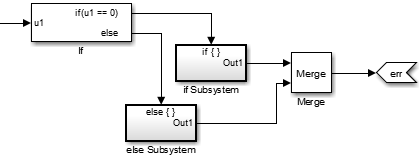
Define an error status output argument for the Simulink Function block that models the AUTOSAR server. Configure the error status argument as the only function output or add it to other outputs. For example, here is a Simulink Function block that returns an error status value in output
err.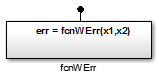
The Simulink Function block implements an algorithm to return error status.
Reference the possible error values type in the model. In the Argument Outport block parameters for the error outport, specify the error status data type, in this case,
appErrType. Set Port dimensions to 1 and Signal type toreal.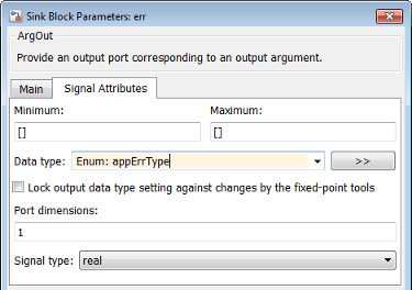
Configure the AUTOSAR properties of the error argument in the client-server interface. Open the AUTOSAR Dictionary, expand C-S Interfaces, and navigate to the Arguments view of the AUTOSAR operation. To add an argument, click the Add button
 . Configure the argument name and set
Direction to
. Configure the argument name and set
Direction to Error.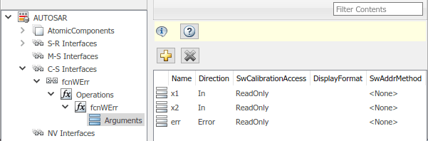
Create an error port in each Function Caller block that models an AUTOSAR client invocation. For example, here is a Function Caller block that models an invocation of
fcnWErr.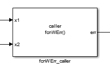
In the Function Caller block parameters, specify the same error status data type.
Configure the AUTOSAR properties of the error argument to match the information in the AUTOSAR Dictionary, Arguments view, shown in Step 4.
The generated C code for the function reflects the configured function signature and the logic defined in the model for handling the possible errors.
appErrType fcnWErr(real_T x1, real_T x2)
{
  appErrType rty_err_0;
  if (...) == 0.0) {
    rty_err_0 = ...;
  } else {
    rty_err_0 = ...;
  }

  return rty_err_0;
}
Additionally, for the enumeration type class definition used in this example, the
build generates header file appErrType.h, containing the possible
error type definitions.
The exported ARXML code contains the possible error definitions, and references to them.
<POSSIBLE-ERRORS>
   <APPLICATION-ERROR …>
      <SHORT-NAME>SUCCESS</SHORT-NAME>
      <ERROR-CODE>0</ERROR-CODE>
   </APPLICATION-ERROR>
   <APPLICATION-ERROR …>
      <SHORT-NAME>ERROR</SHORT-NAME>
      <ERROR-CODE>1</ERROR-CODE>
   </APPLICATION-ERROR>
   …
   <APPLICATION-ERROR …>
      <SHORT-NAME>UNDERFLOW</SHORT-NAME>
      <ERROR-CODE>4</ERROR-CODE>
   </APPLICATION-ERROR>
   <APPLICATION-ERROR …>
      <SHORT-NAME>VALUE_MOD3</SHORT-NAME>
      <ERROR-CODE>5</ERROR-CODE>
   </APPLICATION-ERROR>
</POSSIBLE-ERRORS>
You can use AUTOSAR property functions to programmatically modify the possible errors
that are exported in ARXML code, and to set the Direction property
of a C-S operation argument to Error.
The following example adds UNDERFLOW and VALUE_MOD3 to the possible errors for a C-S
interface named fcnWErr.
>> arProps = autosar.api.getAUTOSARProperties(bdroot)
>> get(arProps,'fcnWErr','PossibleError')
ans =
    'fcnWErr/SUCCESS'    'fcnWErr/ERROR'    'fcnWErr/COMM_MODE…'
    'fcnWErr/OVERFLOW'
>> get(arProps,'fcnWErr/OVERFLOW','errorCode')
ans =
           3
>> add(arProps,'fcnWErr','PossibleError','UNDERFLOW')
>> set(arProps,'fcnWErr/UNDERFLOW','errorCode',4)
>> add(arProps,'fcnWErr','PossibleError','VALUE_MOD3')
>> set(arProps,'fcnWErr/VALUE_MOD3','errorCode',5)
>> get(arProps,'fcnWErr','PossibleError')
ans =
    'fcnWErr/SUCCESS'    'fcnWErr/ERROR'    'fcnWErr/COMM_MODE…'
    'fcnWErr/OVERFLOW'    'fcnWErr/UNDERFLOW'    'fcnWErr/VALUE_MOD3'
You can also access possible errors on a C-S operation. The following example lists
possible errors for operation fcnWErr on C-S interface
fcnWErr.
>> arProps = autosar.api.getAUTOSARProperties(bdroot)
>> get(arProps,'fcnWErr/fcnWErr','PossibleError')
ans =
    'fcnWErr/SUCCESS'    'fcnWErr/ERROR'    'fcnWErr/COMM_MODE…'
    'fcnWErr/OVERFLOW'
The following example sets the direction of C-S operation argument
err to Error.
>> arProps = autosar.api.getAUTOSARProperties(bdroot)
>> set(arProps,'fcnWErr/fcnWErr/err','Direction','Error')
>> get(arProps,'fcnWErr/fcnWErr/err','Direction')
ans =
    Error
Concurrency Constraints for AUTOSAR Server Runnables
The following blocks and modeling patterns are incompatible with concurrent execution of an AUTOSAR server runnable.
Blocks that are inside a Simulink® function:
Blocks with state, such as Unit Delay
Blocks with zero-crossing logic, such as Triggered Subsystem and Enabled Subsystem
Stateflow® charts
Other Simulink Function blocks
Noninlined subsystems
Legacy C function calls with side effects
Modeling patterns inside a Simulink® function:
Writing to a data store memory (for example, per-instance-memory)
Writing to a global block signal (for example, static memory)
To enforce concurrency constraints for AUTOSAR server runnables, use the runnable property canBeInvokedConcurrently. The property is located in the Runnables view in the AUTOSAR Dictionary.
When canBeInvokedConcurrently is set to true for a server runnable, AUTOSAR validation checks for blocks and modeling patterns that are incompatible with concurrent execution of a server runnable. If a Simulink® function contains an incompatible block or modeling pattern, validation reports errors. If canBeInvokedConcurrently is set to false, validation does not check for blocks and modeling patterns that are incompatible with concurrent execution of a server runnable.
You can set canBeInvokedConcurrently to true only for an AUTOSAR server runnable — that is, a runnable with an OperationInvokedEvent. The property canBeInvokedConcurrently is not supported for runnables with other event triggers, such as timing events. If canBeInvokedConcurrently is set to true for a nonserver runnable, AUTOSAR validation fails.
To programmatically set the runnable property canBeInvokedConcurrently, use the AUTOSAR property function set. The following example sets the runnable property canBeInvokedConcurrently to true for an AUTOSAR server runnable named Runnable_readData.
open_system("mControllerWithInterface_server")
arProps = autosar.api.getAUTOSARProperties("mControllerWithInterface_server");
SRPath = find(arProps,[],"Runnable","Name","Runnable_readData")
SRPath = 1×1 cell array
    {'SWC_Controller/ControllerWithInterface_ar/Runnable_readData'}
invConc = get(arProps,"SWC_Controller/ControllerWithInterface_ar/Runnable_readData",...
  "canBeInvokedConcurrently")
invConc = logical
   0
set(arProps,"SWC_Controller/ControllerWithInterface_ar/Runnable_readData",...
  "canBeInvokedConcurrently",true)
invConc = get(arProps,"SWC_Controller/ControllerWithInterface_ar/Runnable_readData",...
  "canBeInvokedConcurrently")
invConc = logical
   1
See Also
Simulink Function | Function Caller | Trigger | Argument Inport | Argument Outport
Topics
- Assemble and Simulate AUTOSAR Software Components in Architecture Model
- Programmatically Configure AUTOSAR Client-Server Communication
- Configure Client-Server Communication AUTOSAR Architectures with System Composer
- Import AUTOSAR XML Descriptions Into Simulink
- Configure AUTOSAR Code Generation
- Model AUTOSAR Communication
- AUTOSAR Component Configuration
- Client-Server Interface