customAntennaStl
Create custom 3-D antenna geometry using STL, STEP, or IGES files
Description
The customAntennaStl object creates a 3-D antenna geometry
and mesh using stereolithography (STL), standard for the exchange of product model data
(STEP), or initial graphics exchange specification (IGES) files. An STL file defines a
3-D surface in the form of points and triangles. While STEP and IGES files save the 3-D
geometry data in ASCII format.
Creation
Description
ca = customAntennaStl
ca = customAntennaStl(PropertyName=Value)PropertyName is the property name and
Value is the corresponding value. You can specify
several name-value arguments in any order as
PropertyName1=Value1,...,PropertyNameN=ValueN.
Properties that you do not specify, retain their default values.
For example, ca =
customAntennaStl(FileName="plate.stl",PhaseShift=10) creates a
custom antenna from the geometry specified in the
plate.stl file and applies a phase shift of 10
degrees to the element.
Properties
Object Functions
axialRatio | Calculate and plot axial ratio of antenna or array |
beamwidth | Beamwidth of antenna |
charge | Charge distribution on antenna or array surface |
createFeed | Create feed at specified location on geometry imported through STL file |
current | Current distribution on antenna or array surface |
efficiency | Calculate and plot radiation efficiency of antenna or array |
EHfields | Electric and magnetic fields of antennas or embedded electric and magnetic fields of antenna element in arrays |
feedCurrent | Calculate current at feed for antenna or array |
impedance | Calculate and plot input impedance of antenna or scan impedance of array |
info | Display information about antenna, array, or platform |
memoryEstimate | Estimate memory required to solve antenna or array mesh |
mesh | Generate and view mesh for antennas, arrays, and custom shapes |
meshconfig | Change meshing mode of antenna, array, custom antenna, custom array, or custom geometry |
msiwrite | Write antenna or array analysis data to MSI planet file |
pattern | Plot radiation pattern of antenna, array, or embedded element of array |
patternAzimuth | Azimuth plane radiation pattern of antenna or array |
patternElevation | Elevation plane radiation pattern of antenna or array |
peakRadiation | Calculate and mark maximum radiation points of antenna or array on radiation pattern |
rcs | Calculate and plot monostatic and bistatic radar cross section (RCS) of platform, antenna, or array |
returnLoss | Calculate and plot return loss of antenna or scan return loss of array |
show | Display antenna, array, AI-based antenna, platform, or shape |
sparameters | Calculate S-parameters for antenna or array |
stlwrite | Write mesh information to STL file |
vswr | Calculate and plot voltage standing wave ratio (VSWR) of antenna or array element |
Examples
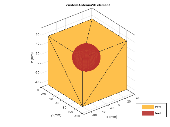
Use geometry files with different extensions to create custom antennas. Create custom 3-D antennas using a customAntennaStl object.
c1 = customAntennaStl(FileName="plateMesh.stl");
c2 = customAntennaStl(FileName="cylinder.step");
c3 = customAntennaStl(FileName="cube.iges");
Create an antenna feed and calculate the antenna impedance at 110 MHz for the first and third antennas and 1 GHz for the second antenna.
c1.createFeed([0 0 0],1);
Z1 = impedance(c1,110e6);
disp(c1)
  customAntennaStl with properties:

          FileName: "plateMesh.stl"
             Units: 'm'
      FeedLocation: [0 0 0]
    AmplitudeTaper: 1
        PhaseShift: 0
     UseFileAsMesh: 0
              Tilt: 0
          TiltAxis: [1 0 0]
c2.createFeed([0 -0.1 -0.05],1);
Z2 = impedance(c2,1e9);
disp(c2)
  customAntennaStl with properties:

          FileName: "cylinder.step"
             Units: 'mm'
      FeedLocation: [0 -0.1000 -0.0500]
    AmplitudeTaper: 1
        PhaseShift: 0
     UseFileAsMesh: 0
              Tilt: 0
          TiltAxis: [1 0 0]
c3.createFeed([-0.05 -0.1 0.05],1);
Z3 = impedance(c3,110e6);
disp(c3)
  customAntennaStl with properties:

          FileName: "cube.iges"
             Units: 'mm'
      FeedLocation: [-0.0500 -0.1000 0.0500]
    AmplitudeTaper: 1
        PhaseShift: 0
     UseFileAsMesh: 0
              Tilt: 0
          TiltAxis: [1 0 0]
Display the structure of custom 3-D antennas.
figure
show(c1)
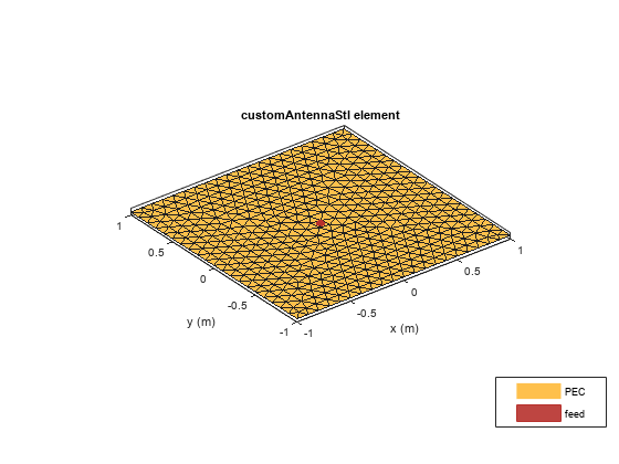
figure
show(c2)
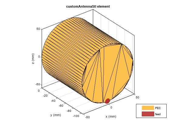
figure
show(c3)
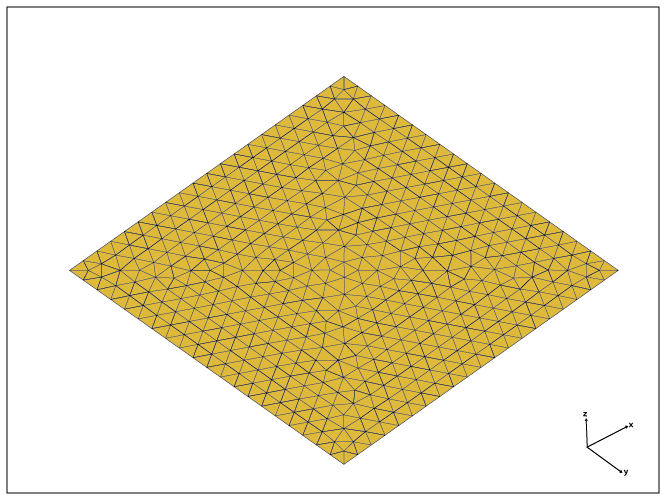
Create a customAntennaStl object using the specified STL file.
ant = customAntennaStl
ant =
  customAntennaStl with properties:

          FileName: []
             Units: 'm'
      FeedLocation: []
    AmplitudeTaper: 1
        PhaseShift: 0
     UseFileAsMesh: 0
              Tilt: 0
          TiltAxis: [1 0 0]
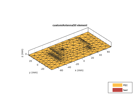
ant.FileName ="patchMicrostrip_ColumnFeed.stl"ant =
customAntennaStl with properties:
FileName: "patchMicrostrip_ColumnFeed.stl"
Units: 'm'
FeedLocation: []
AmplitudeTaper: 1
PhaseShift: 0
UseFileAsMesh: 0
Tilt: 0
TiltAxis: [1 0 0]
Specify the FeedLocation and NumEdges inputs to the createFeed function. Select the edges based on the distance between the feed location and the midpoints of the edges. Edges can be single-feed or a closed polygon.
ant.createFeed([-0.018750000000000 0 0],8) show(ant)
Plot the current distribution at 1.75 GHz.
figure
current(ant,1.75e9,Scale="log")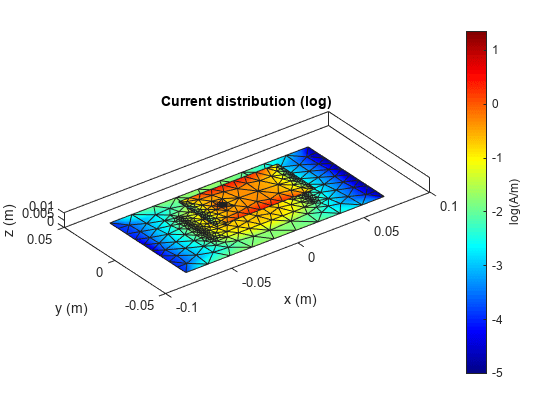
Calculate the impedance at 1.75 GHz.
z = impedance(ant,1.75e9)
z = 83.3968 -52.1467i
Create a customAntennaStl object.
ant = customAntennaStl;
Import the STL files.
ant.FileName = "patchMicrostrip_ColumnFeed.stl";Create the antenna feed using the UI figure window.
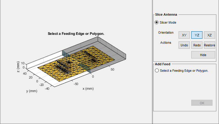
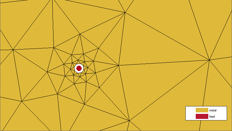
createFeed(ant);
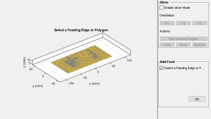
The UI figure window contains the Slice Antenna pane and the Add Feed pane.
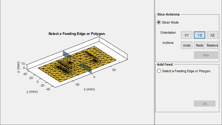
Click Slicer Mode, then click YZ to select the plane along which to slice your antenna.
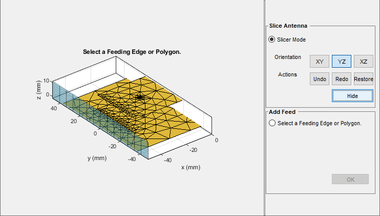
Select the region to hide and then click Hide to hide the selected region.

Repeat the process until you reach the region of interest.
Select Select a Feeding Edge or Polygon under the Add Feed pane to select the desired feeding edge or feeding polygon.

Select the edges of the column that forms a closed polygon. The selected edges must be connected to other edges, otherwise the UI figure window displays an error.
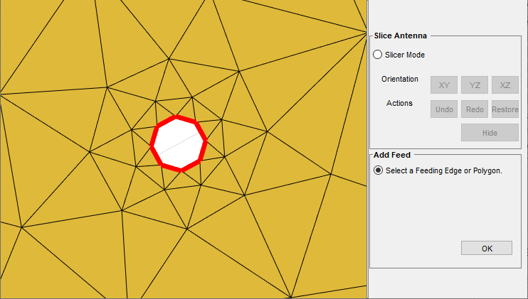
Click OK to define the selected edges as feeding edges. The software displays the structure with the feed.
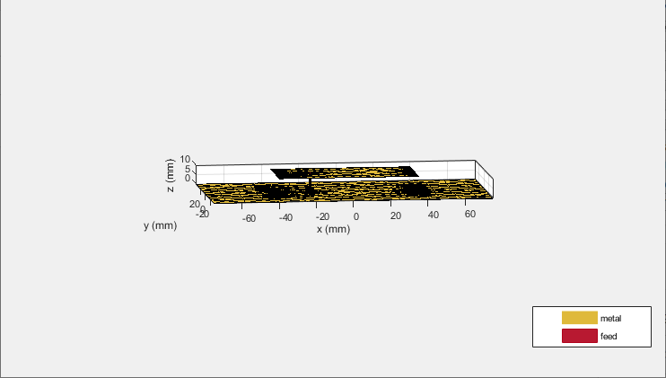
The software also displays the feed location.
Verify the location of the antenna feed.
ant
ant =
  customAntennaStl with properties:

          FileName: "patchMicrostrip_ColumnFeed.stl"
             Units: 'm'
      FeedLocation: []
    AmplitudeTaper: 1
        PhaseShift: 0
     UseFileAsMesh: 0
              Tilt: 0
          TiltAxis: [1 0 0]
References
[1] Balanis, Constantine A. Antenna Theory: Analysis and Design. Fourth edition. Hoboken, New Jersey: Wiley, 2016.