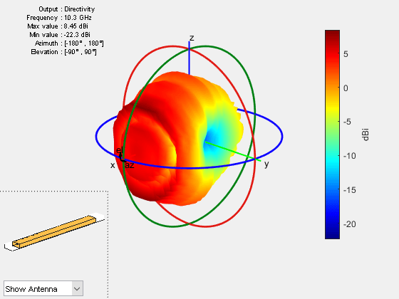
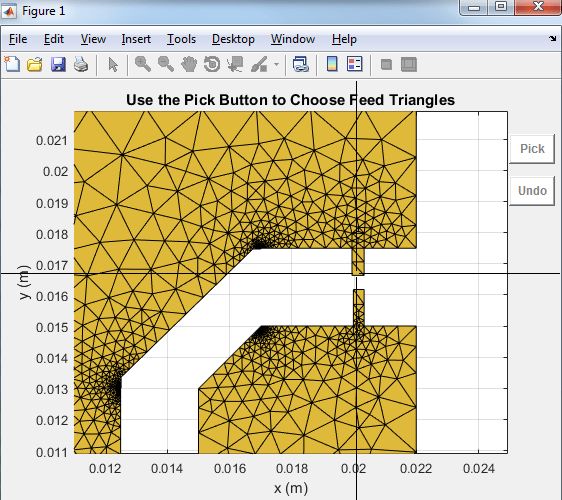
Custom 2-D and 3-D Antenna
Create a custom antenna by importing a planar mesh or defining the antenna geometry using built-in 2-D shapes or shapes created by performing various operations on these built-in shapes.
Use stereolithography (STL) files or shapes with material properties to create custom 2-D or 3-D antenna. Define the feed for this arbitrary element and analyze the antenna or array using existing analysis functions.
Use this custom antenna as an exciter for backing structures, an element in arrays, an element in the platform installed antenna, or an element in the plane wave excitation environment.
Objects
2-D Mesh and Geometry
customAntennaMesh | Create 2-D custom mesh antenna on xy-plane |
customArrayMesh | Create 2-D custom mesh antenna array on xy-plane |
customAntennaGeometry | Create antenna represented by 2-D custom geometry |
customArrayGeometry | Create array represented by 2-D custom geometry |
2-D and 3-D Antenna
customAntenna | Create custom antenna from geometric shapes (Since R2023b) |
customAntennaStl | Create custom 3-D antenna geometry using STL, STEP, or IGES files (Since R2020a) |
2-D Shapes
antenna.Circle | Create circle centered at origin on xy-plane |
antenna.Ellipse | Create ellipse centered at origin on xy-plane (Since R2020a) |
antenna.Polygon | Create polygon on xy-plane |
antenna.Rectangle | Create rectangle centered at origin on xy-plane |
antenna.Triangle | Create triangle on xy-plane (Since R2023a) |
2-D and 3-D Shapes with Material Properties
shape.Circle | Create circle centered at origin on xy-plane (Since R2023b) |
shape.Ellipse | Create ellipse centered at origin on xy-plane (Since R2023b) |
shape.Polygon | Create polygon on xy-plane (Since R2023b) |
shape.Rectangle | Create rectangle centered at origin on xy-plane (Since R2023b) |
shape.Box | Create closed box centered at origin (Since R2023b) |
shape.OpenBox | Create open box centered at origin (Since R2023b) |
shape.Cylinder | Create closed cap cylinder centered at origin (Since R2023b) |
shape.OpenCylinder | Create open cap cylinder centered at origin (Since R2023b) |
shape.Sphere | Create sphere centered at origin (Since R2023b) |
shape.Custom3D | Create custom 3-D shape from other shapes or triangulation (Since R2023b) |
Functions
Shape Operators
add | Boolean unite operation on two shapes |
subtract | Boolean subtraction operation on two shapes |
and | Boolean intersection operation on two shapes |
intersect | Intersection of shape1 and shape2 |
minus | Carve a shape from other shape |
plus | Join two shapes |
area | Calculate area of 2-D shapes in square meters |
getShapeVertices | Find shape vertices (Since R2023b) |
Shape Visualization
Shape Scaling, Rotation, and Mirroring
scale | Change size of shape by fixed factor |
translate | Move shape to new location |
rotate | Rotate shape about axis by angle |
rotateX | Rotate shape about x-axis by angle |
rotateY | Rotate shape about y-axis by angle |
rotateZ | Rotate shape about z-axis by angle |
mirrorX | Mirror shape along x-axis (Since R2022a) |
mirrorY | Mirror shape along y-axis (Since R2022a) |
Shape Modification
createHole | Create a 2-D hole on custom shape (Since R2023b) |
deleteFaces | Delete specified faces of box (Since R2023b) |
extrude | Extrude 2-D shape on another shape (Since R2023b) |
extrudeLinear | Linearly extrude 2-D shape along specified direction (Since R2023b) |
extrudeRotate | Extrude 2-D shape by angle about z-axis (Since R2023b) |
imprintShape | Imprint 2-D shape on another shape (Since R2023b) |
removeFaces | Interactively select and remove 3-D shape faces (Since R2023b) |
Featured Examples
Design and Analyze Perforated Horn Antenna for RF Applications
Design a perforated horn antenna suited for RF applications using custom geometry features of the Antenna Toolbox™ and analyze its scattering parameters. By following this guide, you will learn how to construct the antenna structure step by step, including the waveguide, horn taper, side grids, back grids, top and bottom grids, and finally, integrate feed mechanisms. This example is particularly useful for engineers and researchers focused on antenna design for high-frequency applications.
Analyze Electromagnetic Interference from Shielding Enclosures
Model shielding enclosure using custom 3D shapes and analyze electromagnetic interference due to slots or apertures in enclosure excited by interior sources.
Design And Analyze Spherically Capped Biconical Antenna
Model and analyze a spherically capped biconical antenna using custom 3-D shapes. This antenna is a canonical broadband radiator used in practical ultra-wide-band communication systems. [1] The two cones of the antenna are connected by a cylindrical delta gap feed. The height and diameter of the cylindrical feed are equal. The location of the feed is chosen in between the two cone apex points as the gap between them can be considered as infinitesimally small, which nearly resembles an ideal antenna. Later, the effect of feed dimensions variation and mesh density variation near the delta gap is studied by comparing the antenna input impedance for two different feed diameters and mesh density. The antenna is analyzed in the frequency range of 900MHz to 15GHz.
Analysis of Ultrawideband Trident Inset-Fed Monopole Antenna with Conical Ground
Analyze the performance of a U-shaped monopole antenna designed on a PCB and mounted on a conical ground. You achieve low-frequency matching by inserting a trident inset feed. The conical ground with an elliptical shape at the base of the radiator outperforms traditional UWB monopole designs in impedance-matching bandwidth and radiation pattern omnidirectivity [1].
Analysis of Basic Delta Loop Antenna over Ground
Analyze the performance of a delta loop antenna over a metal ground. The length of the antenna is λ/3 on each side of the triangle, where λ is the wavelength. Equilateral delta antennas are single-band high frequency (HF) antennas. You vary the baseline parameters of an antenna such as the length and height above the ground to optimize antenna performance [1].
Analysis of Edge-Wall Slotted Waveguide Array Antenna for High-Frequency Applications
Analyze the performance of an edge-wall slotted waveguide array antenna. These antennas have many advantages, including high gain, high power handling capacity, and easy manufacturing [1].
Import and Analyze Custom 3-D Antenna Geometry
Simulate a 3-D custom antenna geometry from an STL (stereolithography) file. To simulate a 3-D custom antenna geometry, use the customAntennaStl object. This object allows the user to simulate a custom 3-D geometry from an *.stl file. An STL file is a tessellation of a structure in 3-D space using triangles.
RFID Antenna Design
Design a commercial RFID antenna operating at 915 MHz. This example uses PDE Toolbox™ to draw and mesh the planar structure. The meshed structure is then imported into Antenna Toolbox™ and analyzed for its electromagnetic properties.
Double-Slot Cavity Patch on TMM10 Substrate
Create a custom slot cavity patch using custom antenna geometry and thick dielectric substrate. A double slot cavity patch consists of a double slot patch, backed by a cavity and probe-fed. The cavity is filled with TMM10 substrate. The cavity backing helps to reduce back radiation. You can use this antenna for microwave imaging by placing the antenna close to the human body.
Design And Analyze Spherically Capped Biconical Antenna
Model and analyze a spherically capped biconical antenna using custom 3-D shapes. This antenna is a canonical broadband radiator used in practical ultra-wide-band communication systems. [1] The two cones of the antenna are connected by a cylindrical delta gap feed. The height and diameter of the cylindrical feed are equal. The location of the feed is chosen in between the two cone apex points as the gap between them can be considered as infinitesimally small, which nearly resembles an ideal antenna. Later, the effect of feed dimensions variation and mesh density variation near the delta gap is studied by comparing the antenna input impedance for two different feed diameters and mesh density. The antenna is analyzed in the frequency range of 900MHz to 15GHz.
Design Variations of Microstrip Patch Antenna Using PCB Stack
Use the pcbstack to design basic, parasitic, direct-coupled, and CP patch antennas.
MATLAB Command
You clicked a link that corresponds to this MATLAB command:
Run the command by entering it in the MATLAB Command Window. Web browsers do not support MATLAB commands.

Select a Web Site
Choose a web site to get translated content where available and see local events and offers. Based on your location, we recommend that you select: United States.
You can also select a web site from the following list
How to Get Best Site Performance
Select the China site (in Chinese or English) for best site performance. Other MathWorks country sites are not optimized for visits from your location.
Americas
- América Latina (Español)
- Canada (English)
- United States (English)
Europe
- Belgium (English)
- Denmark (English)
- Deutschland (Deutsch)
- España (Español)
- Finland (English)
- France (Français)
- Ireland (English)
- Italia (Italiano)
- Luxembourg (English)
- Netherlands (English)
- Norway (English)
- Österreich (Deutsch)
- Portugal (English)
- Sweden (English)
- Switzerland
- United Kingdom (English)
Asia Pacific
- Australia (English)
- India (English)
- New Zealand (English)
- 中国
- 日本Japanese (日本語)
- 한국Korean (한국어)


