How to Model Complete and Consistent Requirements
Incomplete and inconsistent requirements cause errors in the design phase that become exponentially more expensive to fix over time. Engineers developing safety-critical applications can save time and money by ensuring their requirements are valid early.
In this video, you will learn:
- What are some common challenges with requirements validation?
- What are engineers doing today to address these challenges?
- Why should you model requirements?
- How to model requirements with the new Requirements Table in Requirements Toolbox and analyze the requirements for completeness and consistency using Simulink Design Verifier
Published: 19 Jan 2022
Incomplete and inconsistent requirements cause errors in the design phase, which become exponentially more expensive to fix over time. Customers developing safety critical applications can save time and money by ensuring their requirements are valid early.
Today, you will learn, what are some common challenges with requirements validation? What are engineers doing today to address these challenges? Why should you model requirements? How to model and validate requirements with a new requirements table and requirements toolbox and Simulink Design Verifier.
In safety critical applications, engineers author requirements primarily with formal logical conditions. These logic driven requirements often represent the majority of the system's requirements. These typically include requirements such as fault detection, signal selection, also known as voting, and mode logic. These requirements are often simple and easy to validate individually.
The challenges emerge when you need to analyze a set of hundreds or thousands of requirements. The top challenges are completeness and consistency. Completeness ensures that all required functionality is defined. Consistency ensures that requirements do not conflict. So what are engineers doing today to address these challenges?
Many organizations create a set of intermediate text-based requirements, which often resemble pseudocode such as this example. Notice the use of variables in the requirement. These variables are often analyzed by text parsing tools to check for consistency and completeness. This process is expensive to create and maintain.
In other words, text is not always the answer. You should model logic-driven requirements. Requirements modeling also called specification modeling provides several advantages over traditional text-based requirements.
These models are mathematically rigorous executable through simulation, easier to author and maintain than pseudocode text requirements, easier to analyze as the requirement set grows, and reusable for downstream verification activities through techniques such as automatic test generation. In Release 2022a, requirements toolbox includes a new requirements table block to allow users to model and analyze logic-driven requirements.
Each row of the table defines a requirement. A requirement includes a summary, which is a text-based description of the requirement, a precondition, an expression which defines the conditions where the requirement is valid. This expression is written using MATLAB code. An optional duration, which describes the time in seconds during which the precondition must be satisfied. A postcondition, and expression, which defines the conditions that must be achieved when the precondition is met.
You can express a variables range using standard syntax, such as parentheses and brackets. You can also define an optional action, which defines what actions are performed if the precondition is valid. Such as calling a function or assigning a value.
Finally, there are built in temporal operators. Let's walk through a real world example. Requirements for a DC charging code for an electric vehicle. Will build the requirements around a standard J-Plug. In DC charging, the electric vehicle battery is directly connected to the charging station. Due to safety concerns with voltage exposure at the port, DC charge cords are required to be locked during charging.
Based on the J1772 specification, we can define three requirements for the system. Requirement one, the electric vehicle shall lock the charger in place if the electric vehicle supply equipment is compatible. Requirement two, the electric vehicle shall unlock the cord. If the acknowledged terminate charging session signal is received and the vehicle measures an input voltage that is less than 60 volts during normal shutdown procedures. Requirement three, the electric vehicle shall unlock the cord If the pilot status is not ready and the vehicle measures an input voltage that is less than 60 volts during an emergency shutdown.
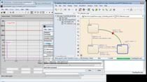
Let's use a requirements table to define these requirements. I have already defined the first two requirements and have written a brief summary for the third requirement. The postcondition column defines the expected condition of the lock command.
Let's define the third requirement. First, let's define the precondition using a simple MATLAB expression. The postcondition is that the code is unlocked. Now that we have defined the three requirements, let's analyze the table to ensure completeness and consistency. To do this, just click the Analyze button.
This will launch Simulink Design Verifier to automatically analyze the table. It looks like the requirements have issues with inconsistency and incompleteness. The report provides an example for each issue. A requirement is inconsistent when the block can perform different behaviors for a single combination of input values.
In other words, there are two or more conflicting requirements. In this case, there is an inconsistency between the first and third requirements. Under the condition shown, requirement one demands the core to be locked while requirement three demands the cord to be unlocked.
Note that the scope of requirement one is only at the beginning of the charging. By adding this information to the precondition of requirement one, we can alleviate the inconsistency. Requirements have incompleteness issues when the block does not comprehensively specify outputs for possible input values.
In other words, the expected functionality has not been fully defined. In this case, the expected functionality for the lock command based on the inputs is incomplete. Basically, the requirements do not specify what the lock command should be if the vehicle is in normal shutdown, and the port voltage is still unsafe.
To address this, we'll need to add new requirements. This is an iterative process. In most cases, you will need to continue updating requirements until there are no remaining issues with inconsistency and incompleteness. Here is the final result. Real systems have physical limitations which should be accounted for in the requirements.
We can define these using assumptions. In this case, there are three assumptions for the charging status. These assumptions will be used when analyzing the table. When you create a requirement in a requirements table, the block automatically creates a requirement, you can manage in the requirements editor.
You can use the requirements editor to link requirements in the requirements table to model elements. And view traceability data using a traceability matrix or traceability diagram. This demo showed you how to model a set of logic-driven requirements in a requirements table, and analyze the requirements to ensure completeness and consistency. This will help ensure these requirements are valid before beginning the design. To get started, check out the example in requirements toolbox.