이동 로봇의 아키텍처 및 활동 다이어그램 설계
System Composer™에서 아키텍처 모델은 다양한 추상화 수준에서 시스템을 설명합니다. 이 이동 로봇 예제에서는 두 가지 아키텍처를 소개합니다.
논리 아키텍처 — 각 서브시스템의 전자 하드웨어와 소프트웨어 컴포넌트 간의 데이터 교환 설명
물리 아키텍처 — 로봇에 필요한 물리 하드웨어 또는 플랫폼 설명
이러한 아키텍처 모델 외에도, 상위 수준의 기능과 해당 기능들 간의 관계를 설명하는 활동 다이어그램을 생성할 수 있습니다. 한 아키텍처에서 다른 아키텍처로의 요소 간 유방향 관계, 또는 활동 다이어그램에서 아키텍처로의 요소 간 유방향 관계를 나타내려면 [Allocation Editor]를 사용하십시오.
참고
이 예제에서는 Simscape™ 블록을 사용합니다. Simscape 라이선스가 없는 경우, 모델을 열 수는 있는데 블록 파라미터 수정과 같은 기본적인 변경만 가능합니다.
아키텍처 모델 설계, 지정 및 할당하기
이 이동 로봇 프로젝트에는 요구 사항을 컴포넌트에 연결하고 할당을 정의할 수 있는 아키텍처 모델이 포함되어 있습니다. 프로젝트에 기능 설계를 정교화하고 대체 옵션을 모색하기 위한 활동 다이어그램도 포함되어 있습니다.
프로젝트를 시작합니다.
openProject("scMobileRobotExample");이동 로봇의 기능 흐름 활동 다이어그램
기능 흐름 활동 다이어그램은 이동 로봇이 임의의 시작점과 임의의 끝점 사이를 이동하는 운용 시나리오를 설명합니다. 알고리즘이 경로를 계획합니다. 경로가 너무 길고 로봇의 배터리 수명이 충분하지 않으면 프로세스가 조기에 종료됩니다. 경로가 실현 가능한 경우 로봇은 설정된 각도 방향에서 시작하여 x 방향으로 이동하고 y 방향으로 이동한 다음 최종 각도 방향을 설정합니다.
systemcomposer.openModel("RobotActivity");
이동 로봇의 논리 아키텍처 모델
논리 아키텍처 모델은 시뮬레이션을 위한 이동 로봇 시스템의 거동을 설명합니다. 여기에는 궤적 생성기, 궤적 팔로워, 모터 제어기, 센서 알고리즘, 로봇 및 환경이 포함됩니다. 연결은 시스템 내의 상호 작용을 나타냅니다. 논리 아키텍처 모델을 열려면 파일을 더블 클릭하거나 이 명령을 실행하십시오.
systemcomposer.openModel("scMobileRobotLogicalArchitecture");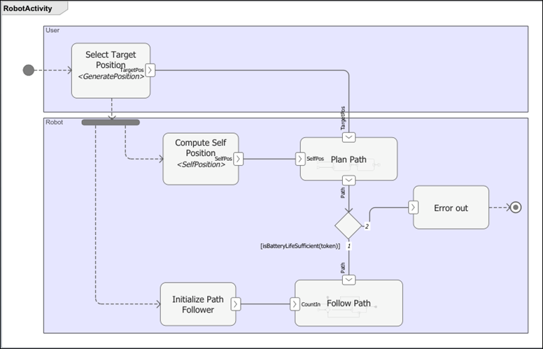
이동 로봇의 물리 아키텍처 모델
물리 아키텍처 모델은 하드웨어 컴포넌트와 그 연결을 설명합니다. 여기에는 센서, 액추에이터, 임베디드 프로세서가 포함됩니다. 색과 아이콘은 각 요소에 사용되는 스테레오타입을 나타냅니다. 물리 아키텍처 모델을 열려면 파일을 더블 클릭하거나 이 명령을 실행하십시오.
systemcomposer.openModel("scMobileRobotHardwareArchitecture");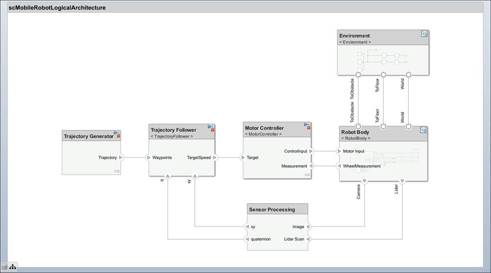
컴포넌트에 요구 사항 연결하기
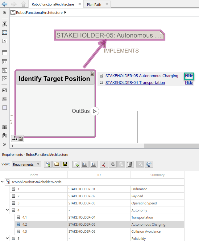
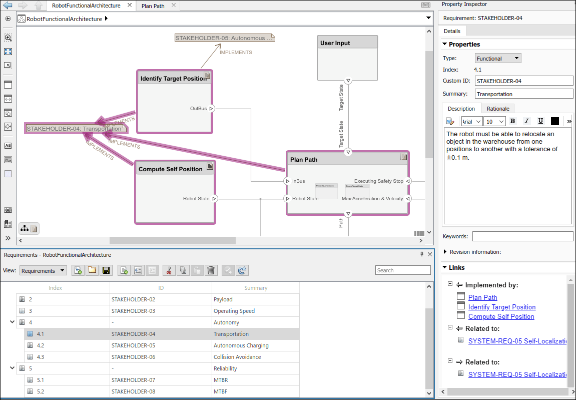
요구 사항 추적성은 기술적 요구 사항을 아키텍처 모델의 컴포넌트와 포트에 연결하여 초기 요구 사항 단계와 시스템 수준 설계 간에 연결이 가능하도록 합니다. 컴포넌트를 이해관계자 요구 사항(stakeholder needs)에 다시 연결하여 요구 사항이 충족되는지 여부를 쉽게 추적할 수 있습니다. 요구 사항을 컴포넌트로 끌어서 놓아 요구 사항 링크를 추가할 수 있습니다.
요구 사항을 보려면 [Apps] > [Requirements Manager]로 이동하여 [Requirements Manager]를 여십시오.
물리 아키텍처 모델의 Payload 컴포넌트는 Maximum Payload 요구 사항 SYSTEM-REQ-03을 구현합니다. 연결된 요구 사항을 표시하거나 숨기려면 컴포넌트의 오른쪽 위 코너에 있는 요구 사항 아이콘을 클릭합니다.

논리 아키텍처 모델에 연결된 요구 사항은 [Requirements Browser]에서 볼 수 있습니다. SYSTEM-REQ-10을 선택하면 Sensor Life 요구 사항과 관련된 컴포넌트만 표시됩니다.
아키텍처 및 다이어그램 할당하기
모델 간 할당을 사용하여 물리 컴포넌트에 기능 컴포넌트를 할당할 수 있습니다. Allocation Editor를 열려면 [Modeling] > [Allocation Editor]로 이동하거나 이 명령을 실행합니다.
systemcomposer.allocation.editor
할당 세트를 불러옵니다.
allocSetPhys = systemcomposer.allocation.load("LogicalToPhysicalAllocation");
allocSetAct = systemcomposer.allocation.load("DiagramToModel");
논리 아키텍처에 기능 활동 다이어그램 할당하기
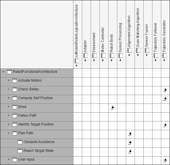
DiagramToModel 할당 세트 아래에서 Scenario 1을 선택합니다.
[Row Filter] 섹션과 [Column Filter] 섹션에서 [Component]를 선택합니다. Allocation Editor 툴을 사용하면 서로 다른 아키텍처 모델 간의 컴포넌트를 연결하여 프로젝트에 대한 추적성을 설정할 수 있습니다. 할당 행렬의 상자를 더블 클릭하여 두 개 요소를 할당하거나 할당 해제합니다.
활동 다이어그램에서 액션 노드 Initialize Path Follower, Apply Path Limits, Select Target Position, Error out을 논리 아키텍처 모델의 Alignment Algorithm 컴포넌트에 할당하여 이러한 액션이 해당 논리 컴포넌트의 내용에 의해 제어된다는 것을 나타냅니다.
물리 아키텍처에 논리 아키텍처 할당하기
LogicalToPhysicalAllocation 할당 세트 아래에서 Scenario 1을 선택합니다.
차량의 자율성은 주로 타깃 머신에 의해 처리되는데, 타깃 머신은 센서 측정값을 처리하여 제어 입력값을 계산하는 임베디드 컴퓨터입니다. 따라서 Robot Body, Sensor Fusion, Trajectory Generator와 같은 많은 기능 컴포넌트가 물리 아키텍처 모델의 Target Machine 컴포넌트에 할당됩니다.
참고 문헌
[1] Rahman, Mohd Azizi Abdul, Katsuhiro Mayama, Takahiro Takasu, Akira Yasuda, and Makoto Mizukawa. “Model-Driven Development of Intelligent Mobile Robot Using Systems Modeling Language (SysML).” In Mobile Robots: Control Architectures, Bio-Interfacing, Navigation, Multi Robot Motion Planning and Operator Training, edited by Janusz Będkowski. InTech Open, 2011. https://doi.org/10.5772/26906.
참고 항목
allocate | addComponent | addPort | connect