Design SoC Model Using System Composer
System Composer™, in combination with SoC Blockset™, enables you to define and design a software application to run on a system-on-chip (SoC) device. This allows preliminary analysis of your design, for example, analyze whether the software tasks in your application can be scheduled on your chosen hardware. For a general workflow on authoring an architecture model in System Composer, see Compose and Analyze Systems Using Architecture Models (System Composer).
Author Architecture Model of Software System
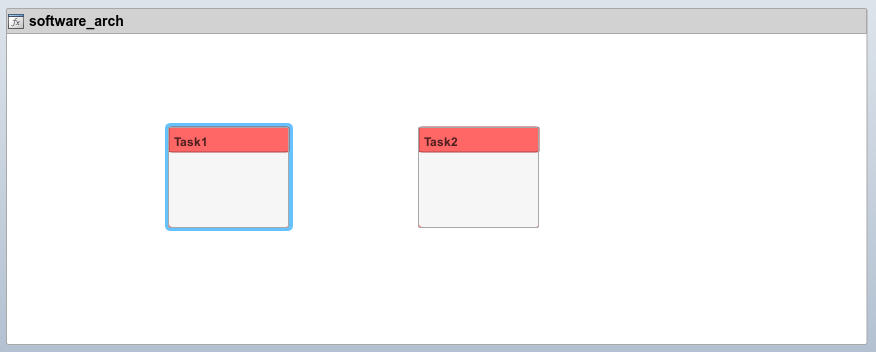
First author a System Composer architecture model of a software system for an SoC device. As an example, consider an application with two software tasks.
Create a new architecture. From the Simulink® toolstrip, on the Simulation tab, select New > Architecture.
On the Simulink Start Page, select System Composer > Software Architecture Model.
Apply the
soc_blockset_profileprofile. On the Modeling tab, select Profile Editor > Import. Navigate and choose the XML file<matlabroot>/toolbox/shared/soc/processor/utilities/soc_blockset_profile.xml.Add two
Component(System Composer) objects to the architecture model.Specify the components as a periodic and aperiodic software tasks. Right-click the component, and select Apply Stereotype > soc_blockset_profile.PeriodicSoftwareTask and Apply Stereotype > soc_blockset_profile.AperiodicSoftwareTask, respectively.
In each component, specify the properties of the tasks, such as
MeanExecutionTimeandCoreAffinity.
This figure shows the resulting architecture model for the SoC software system.
Author Architecture Model of Hardware System
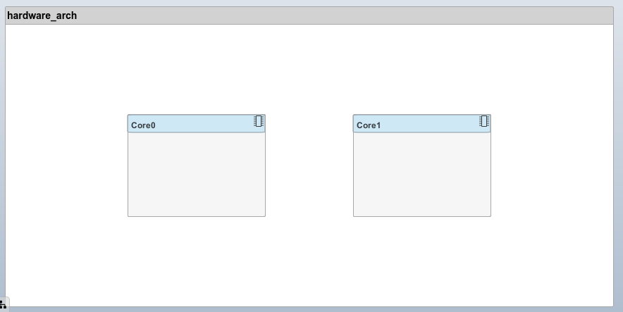
Author a System Composer architecture model of the hardware system, specifically the processor system for an SoC device. As an example, consider the hardware with two cores.
Create a new architecture. From the Simulink toolstrip, on the Simulation tab, select New > Architecture.
On the Simulink Start Page, select System Composer > Architecture Model.
Apply the
soc_blockset_profileprofile. In the Modeling tab, select Profile Editor > Import. Navigate and choose the XML file<matlabroot>/toolbox/shared/soc/processor/utilities/soc_blockset_profile.xml.Add two
Component(System Composer) objects to the architecture model.Specify each component as a processor cores. Right-click the component, and select Apply Stereotype > soc_blockset_profile.ProcessorCore.
In each component, assign the
Coreproperty of each component to the cores available in the processor.
This figure shows the resulting architecture model for the SoC processor system.
Allocate Processor Resources
Using the processor and software architecture models that you, defined in the previous sections, create a specification in System Composer where the software tasks you allocate to specific cores in the processor. The specification can include multiple implementation scenarios, where the tasks are allocated to cores in various combinations. SoC Blockset can then analyze whether these scenarios can be realized with the given task properties.
Open the Allocation Editor (System Composer) app. From the Simulink toolstrip, on the Views tab, click Allocation Editor.
In the Create Allocation Set window, specify the name of the allocation set such as
MyAllocation, set Source Model to the software architecture model, and set Target Model to the processor architecture model.In the scenario table, click the intersection between
Task1andCore1. Under Allocation Properties, select the Allocated check box. Repeat this step forTask2andCore2. The resulting allocation diagram should be similar to the image shown.
Save the allocation set. In the toolstrip, click the Save Allocation Set button to generate an MLDATX file.
You can repeat this process for any number of tasks and cores, assigning multiple tasks to a single core.
Analyze Scheduling Constraints
The allocation set for the software tasks and their assigned processor cores can help
you determine if a software system has sufficient processing time to schedule the tasks.
Using the socTaskSchedulability function from SoC Blockset, you can get metrics that indicate whether the total system and individual
tasks can be scheduled. With the default task specifications that you defined earlier
for the software task components, socTaskSchedulability generates
these statistics.
[schedulable,tasks,cores] = ...
    socTaskSchedulability("MyAllocation.mldatx","Scenario 1");
>> tasks(1)

ans =

  struct with fields:

           name: 'Task1'
    schedulable: 1
>> cores(1)
ans =
struct with fields:
name: '0'
usage: 1.0000e-04The results show that the system can be scheduled and only 0.01% of the processor core time is occupied. Based on this result, you can determine whether the system specification needs to change to meet the design requirements. For example, you could reallocate the software tasks to cores to achieve more balanced core usage.
Transform Software System Architecture to SoC Blockset Model
After authoring your system in System Composer, you can create an equivalent SoC Blockset model using the socCreateModel function. Using the software and architecture model that
you created earlier, socCreateModel function creates the top-level
and processor SoC models shown.
socCreateModel("MyAllocation.mldatx","Scenario 1")


You can then connect and modify the generated SoC models to create your deployable SoC model application.
See Also
soc_blockset_profile | ProcessorCore | PeriodicSoftwareTask | socCreateModel | socTaskSchedulability