Multibody Explorer
R2026bVisualize and explore multibody models
Description
Use the Multibody Explorer tool to interactively visualize and explore multibody models. The tool consists of the Model Tree pane, the Properties pane, and a visualization pane.
With the Multibody Explorer, you can:
Interactively View Configurations: View the model configuration in the visualization pane.
Explore Model Hierarchy: Navigate through the model hierarchy using the model tree.
Examine and Update Parameters: Access and modify component parameters by using the Properties pane.
Dynamic Camera Management: Enhance model visualization by creating and editing dynamic cameras using the Camera Manager.
Video Creation and Configuration: Produce and configure videos of multibody animations by using the Video Creator.
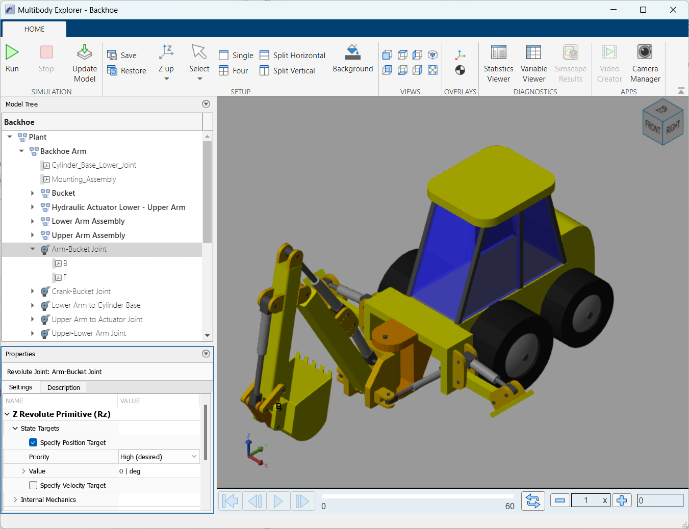
Open the Multibody Explorer
By default, Multibody Explorer opens when you update or simulate a multibody model. If Multibody Explorer does not open:
In the Simulink Toolstrip, on the Modeling tab, select Model Settings.
In the left pane of the Configuration Parameters dialog box, navigate to Simscape Multibody > Explorer.
Select the Open Multibody Explorer on model update or simulation check box.
Examples
This example shows how to specify views of multibody models using the Multibody Explorer. In the visualization pane, you can interactively examine the body geometries, mechanical connections, and trajectories of a multibody model in 3-D space. To view model details, you can adjust the views of a model. You can change the view by:
Selecting a standard view.
Using the view selection cube or orientation triad.
Rotating, panning, and zooming.
In this example, you explore a model of a robotic arm.
Select a Standard View
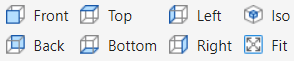
Use the seven standard views to change the perspective of a multibody model. To select a standard view, in the Multibody Explorer toolstrip, on the Views tab, click one of the standard view buttons.
Use View Selection Cube and Orientation Triad
You can use the view selection cube and the orientation triad to manipulate the view of a model. Use the View Selection Cube, located in the upper-right corner of the visualization pane, to select different model views. By clicking on the faces, edges, and corners of the cube, you can access corresponding views of the model. For example, clicking the front face of the cube shows the front view of the model in the visualization pane, while clicking the corner shared by the front, top, and right faces shows the ISO view.
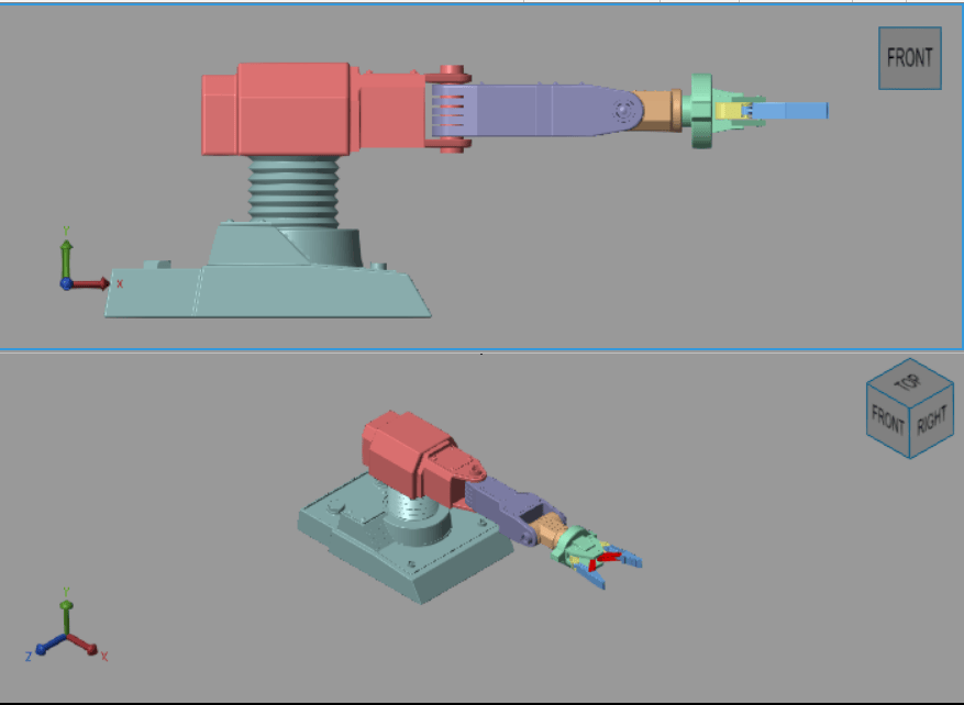
Use the orientation triad, in the bottom-left corner of the visualization pane, to orient the model view. For instance, clicking on the x-, y-, or z-axis of the triad makes the selected axis perpendicular to the screen.
Rotating, Panning, and Zooming
To view your model from an arbitrary perspective or at different zoom levels, use these buttons in the Multibody Explorer toolstrip:
 — Rotate the camera about a general 3-D axis.
 — Roll the camera around its current aim axis.
 — Move the camera in the current visualization plane.
 — Increase or decrease the camera zoom level.
 — Adjust the camera zoom to focus on a selected region.
You can also use keyboard and mouse shortcuts to navigate the model. This table summarizes the available shortcuts:
Action | Shortcut |
Rotate | 1. Click and hold the mouse scroll wheel. 2. Move the mouse in the desired direction to rotate the model. |
Pan | 1. Press and hold Shift key. 2. Click and hold the mouse scroll wheel. 3. Move the mouse in the desired direction to pan the model. |
Zoom | 1. Press and hold Ctrl key. 2. Click and hold the mouse scroll wheel. 3. Move the mouse up to zoom in, down to zoom out. |
Fit to view | Press Space key. |
Use Multiple Visualization Tiles
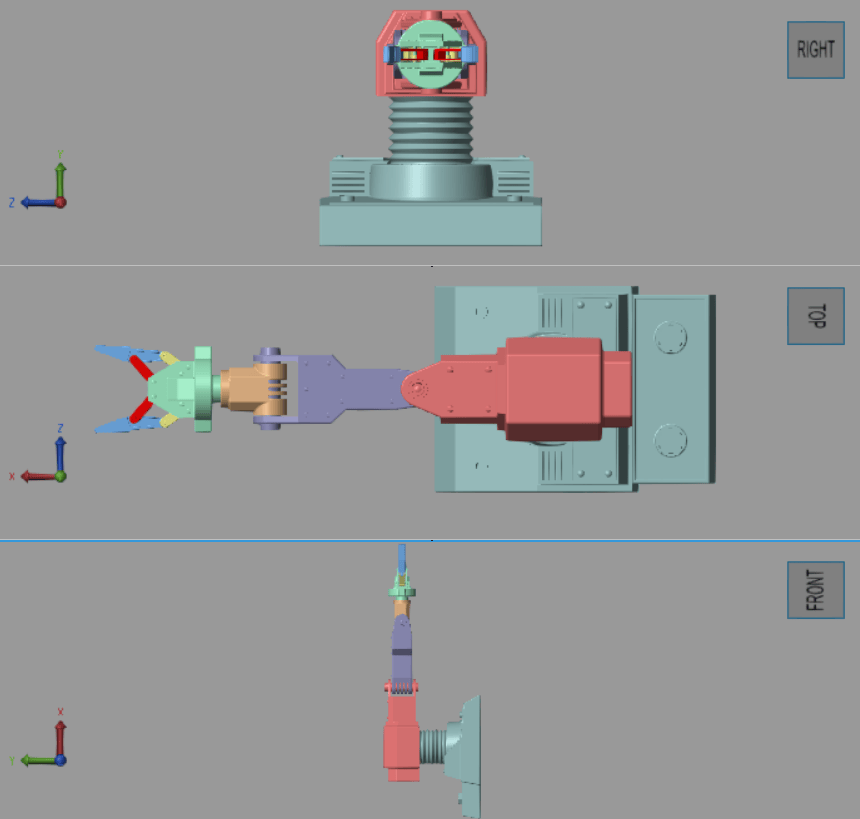
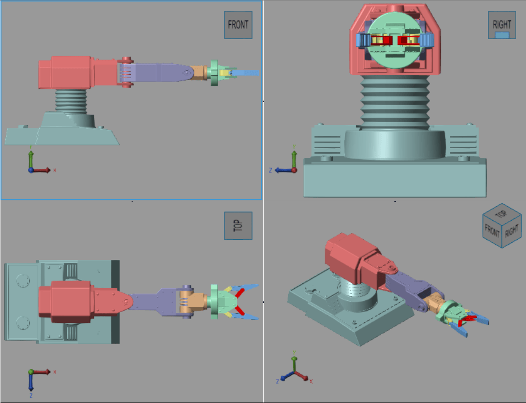
To observe a model from different perspectives simultaneously, in the toolstrip, on the Setup section, uses these buttons to split the visualization pane into multiple tiles:
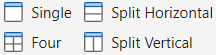
You can at most have four tiles in the visualization pane. You can merge two tiles by clicking the black dot between the tiles. To ensure that the resulting tile uses the view point of one or the other tile, select that tile first before clicking the black dot between the tiles.
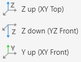
The view convention determines the perspective from which you view your model. To specify view conventions, in the Setup section, select one of these options:
This example shows how to use the Properties pane to update parameters of components and subsystems in a multibody model.
Open the example and run the FourBar model.
Update the Crank Link Length
In the four-bar model, the Crank Link is a subsystem that represents the crank link, including its length, density, and color. To update the parameters of this subsystem, follow these steps:
In the Model Tree pane, select Crank Link. The Properties pane shows the parameters for the
CrankLinksubsystem.
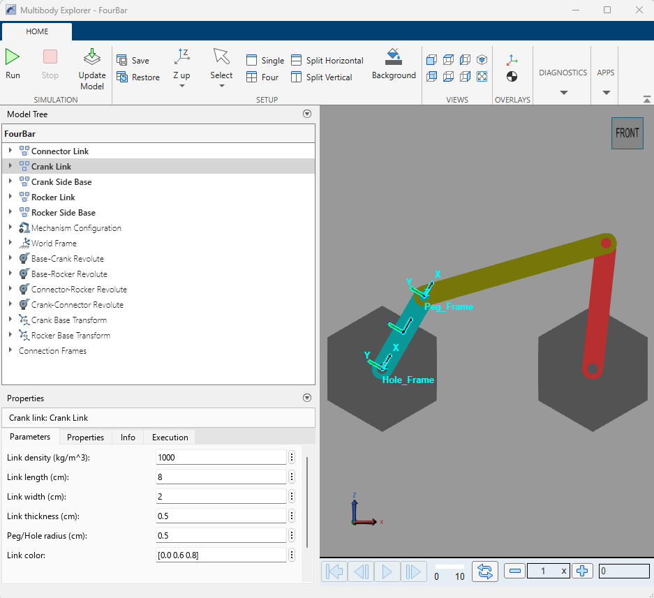
To change the length set Link length (cm) to 5
cm.In the Multibody Explorer toolstrip, on the Simulation tab, click Update Model
 .
.
Specify Joint Position Target
You can specify properties for the components in the model, such as a joint block. To set the position target of the base-crank revolute joint, use the Properties pane and follow these steps:
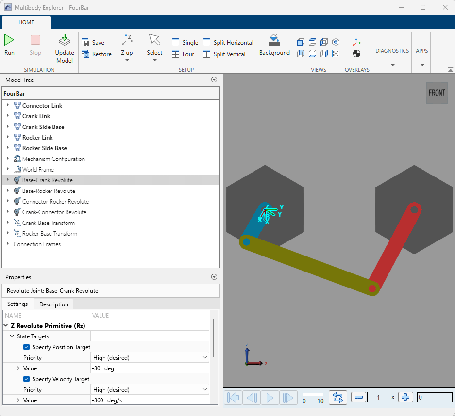
In the Model Tree pane, select Base-Crank Revolute. The Properties pane shows the parameters of the joint.
In the Properties pane, navigate to Z Revolute Primitive (Rz) > State Targets > Specify Position Target. In the Value field, enter -30
deg.In the Multibody Explorer toolstrip, on the Simulation tab, click Update Model
 .
.
The image shows the updated system.
Related Examples
Parameters
Limitations
On macOS platforms, the Multibody Explorer runs at a low frame rate if the model has a geometry with a large number of triangles or vertices. To mitigate this issue:
For Extruded Solid or Revolved Solid blocks, reduce the number of points in the cross-sections.
For File Solid blocks, use CAD files with fewer vertices.
The Multibody Explorer does not support visualization for Model References. To resolve this issue, turn off the visualization for referenced models:
In the Simulink Toolstrip, on the Modeling tab, select Model Settings.
In the left pane of the Configuration Parameters dialog box, navigate to Simscape Multibody > Explorer.
Clear the Open Multibody Explorer on model update or simulation check box.
Tips
After you click Save, you must also save the Simulink model for the view configuration to persist in future sessions.
Component visibility, including whether components are shown or hidden, is a session-only setting. The Save and Restore buttons do not capture or restore which components are hidden or shown.
If you split the visualization into multiple views, show and hide actions apply to all views simultaneously. You cannot hide a component in one view while showing it in another.
In the Model Tree pane, components displayed in bold font are visible in the visualization pane, while components displayed in normal font are hidden.
The Results Explorer button requires simulation log data. Run or replay a simulation before opening the Results Explorer.

