Tune a Control System Using Control System Tuner
This example shows how to use the Control System Tuner app to tune a MIMO, multiloop control system modeled in Simulink®.
Control System Tuner lets you model any control architecture and specify the structure of controller components, such as PID controllers, gains, and other elements. You specify which blocks in the model are tunable. Control System Tuner parameterizes those blocks and tunes the free parameters system to meet design requirements that you specify, such as setpoint tracking, disturbance rejection, and stability margins.
Control System Model
This example uses the Simulink model rct_helico. Open the model.
open_system('rct_helico')
The plant, Helicopter, is an 8-state helicopter model trimmed to a steady-state hovering condition. The state vector x = [u,w,q,theta,v,p,phi,r] consists of:
Longitudinal velocity
u(m/s)Normal velocity
w(m/s)Pitch rate
q(deg/s)Pitch angle
theta(deg)Lateral velocity
v(m/s)Roll rate
p(deg/s)Roll angle
phi(deg)Yaw rate
r(deg/s)
The control system of the model has two feedback loops. The inner loop provides static output feedback for stability augmentation and decoupling, represented in the model by the gain block SOF. The outer loop has a PI controller for each of the three attitude angles. The controller generates commands ds,dc,dT in degrees for the longitudinal cyclic, lateral cyclic, and tail rotor collective using measurements of theta, phi, p, q, and r. This loop provides the desired setpoint tracking for the three angles.
This example uses these control objectives:
Track setpoint changes in
theta,phi, andrwith zero steady-state error, rise times of about 2 seconds, minimal overshoot, and minimal cross-coupling.Limit the control bandwidth to guard against neglected high-frequency rotor dynamics and measurement noise. (The model contains low-pass filters that partially enforce this objective.)
Provide strong multivariable gain and phase margins. (Multivariable margins measure robustness to simultaneous gain or phase variations at the plant inputs and outputs. See the
diskmarginreference page for details.)
Set Up the Model for Tuning
Using Control System Tuner, you can jointly tune the inner and outer loops to meet all the design requirements. To set up the model for tuning, open the app and specify which blocks of the Simulink model you want to tune.
In the Simulink model window, under Control Systems in the Apps tab, select Control System Tuner.
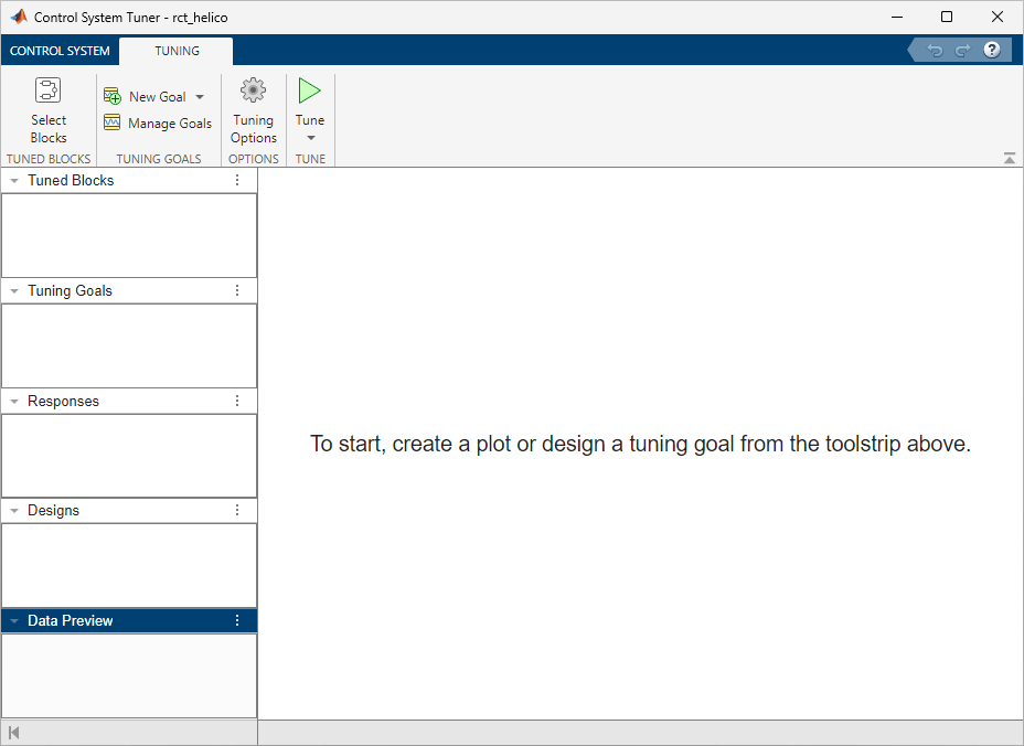
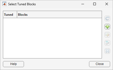
In Control System Tuner, on the Tuning tab, click Select Blocks. Use the Select Tuned Blocks dialog box to specify the blocks to tune.
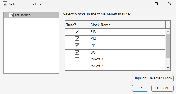
Control System Tuner analyzes your model to find blocks that can be tuned. For this example, the controller blocks to tune are the three PI controllers and the gain block. Check the corresponding blocks PI1, PI2, PI3, and SOF.
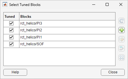
Click OK. The Select Tuned Blocks dialog box now reflects the blocks you added.
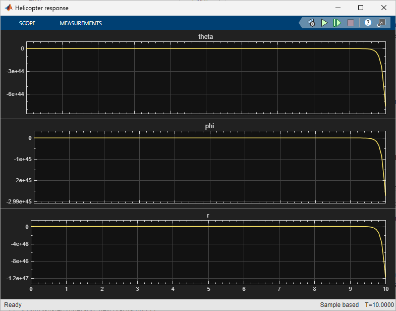
When you select a block to tune, Control System Tuner automatically parameterizes the block according to its type and initializes the parameterization with the block value in the Simulink model. In this example, the PI controllers are initialized to and the static output-feedback gain is initialized to zero on all channels. Simulating the model shows that the control system is unstable for these initial values.
Specify Tuning Goals
The design requirements for this system, discussed previously, include setpoint tracking, minimum stability margins, and a limit on fast dynamics. In Control System Tuner, you capture design requirements using tuning goals.
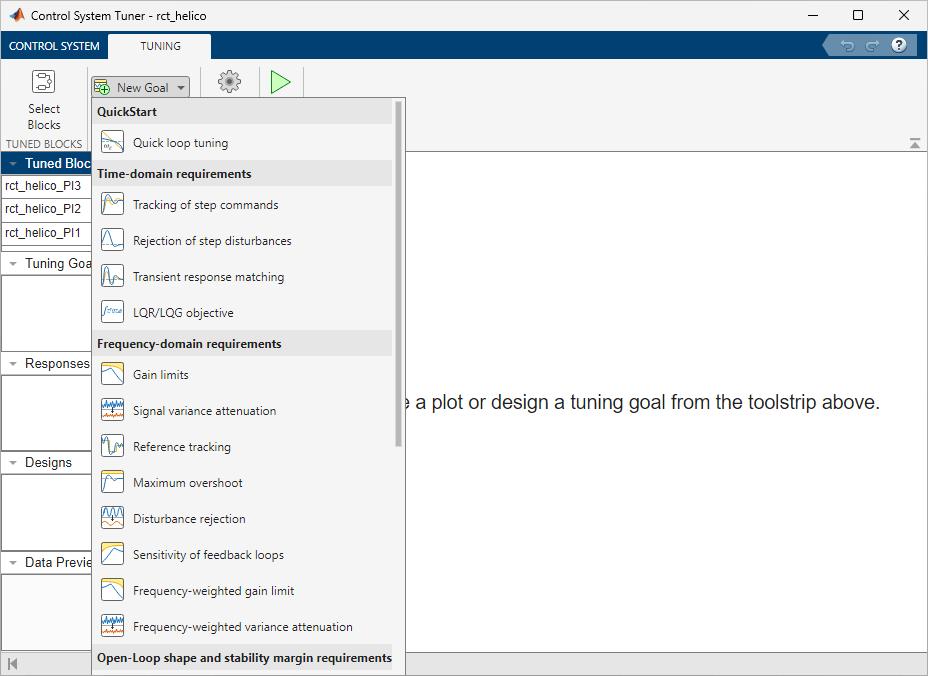
First, create a tuning goal for the setpoint-tracking requirement on theta, phi, and r. On the Tuning tab, in the New Goal drop-down list, select Tracking of step commands.
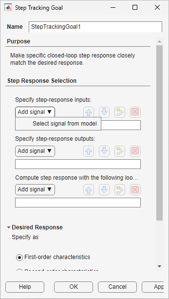
In the Step Tracking Goal dialog box, specify the reference signals for tracking. Under Specify step-response inputs, click Add signal to list. Then click Select signal from model.
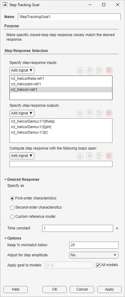
In the Simulink model editor, select the reference signals theta_ref, phi_ref, and r_ref. These signals appear in the Select signals dialog box. Click Add Signal(s) to add them to the step tracking goal.
Next, specify the outputs that you want to track those references. Under Specify step-response outputs, add the outputs theta, phi, and r.
The requirement is that the responses at the outputs track the reference commands with a first-order response that has a one-second time constant. Enter these values in the Desired Response section of the dialog box. Also, for this example set Keep mismatch below to 20. This value sets a 20% relative mismatch between the target first-order response and the tuned response.
This figure shows the configuration of the Step Tracking Goal dialog box. Click OK to save the tuning goal.
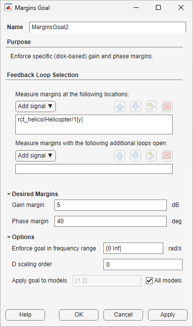
Next, create tuning goals for the desired stability margin requirements. For this example, the multivariable gain and phase margins at the plant inputs u and plant outputs y must be at least 5 dB and 40 degrees. Create separate tuning goals for the input and output margin constraints. In the New Goal drop-down list, select Minimum stability margins. In the Margins Goal dialog box, add the input signal u under Measure stability margins at the following locations. Also, enter the gain and phase values 5 and 40 in the Desired Margins section of the dialog box. Click OK to save the input stability margin goal.

Create another Margins Goal for the output stability margin. Specify the output signal y and the target margins, as shown, and save the output stability margin goal.
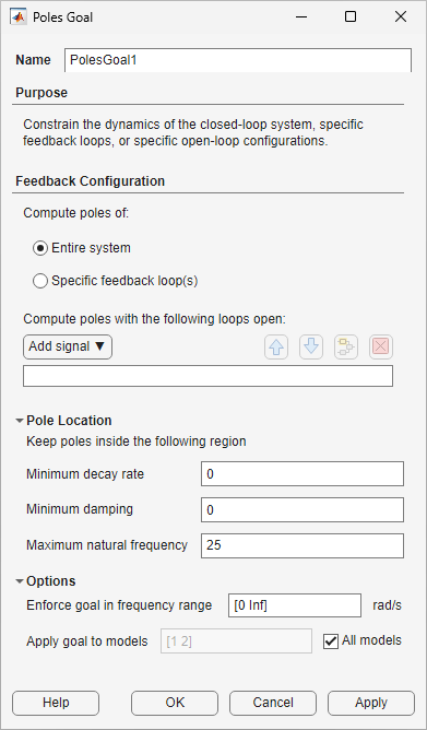
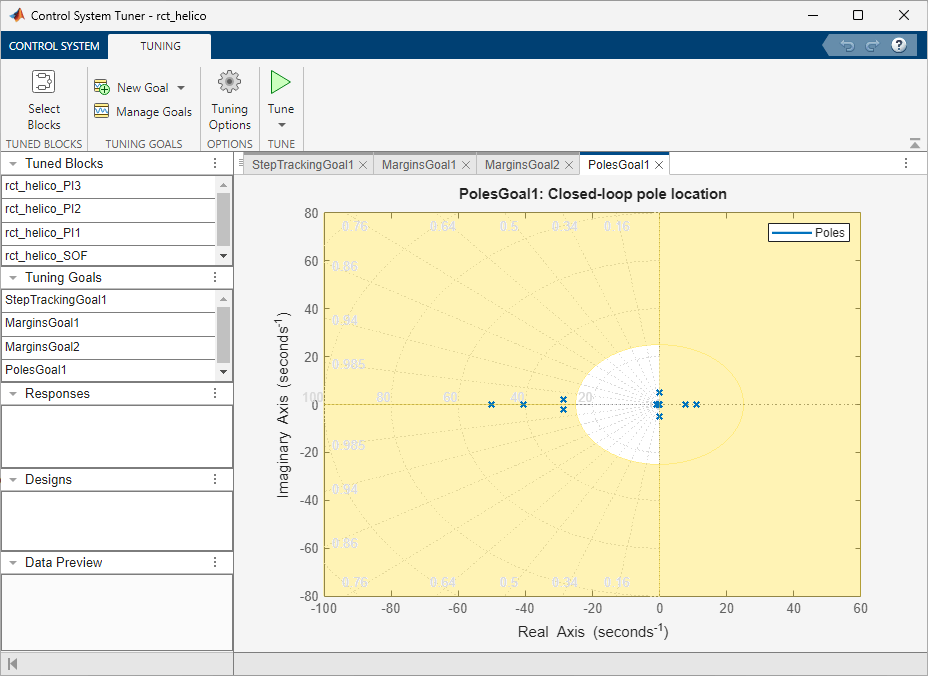
The last requirement is to limit fast dynamics and jerky transients. To achieve this, create a tuning goal that constrains the magnitude of the closed-loop poles to less than 25 rad/s. In the New Goal drop-down list, select Constraint on closed-loop dynamics. In the Poles Goal dialog box, specify the maximum natural frequency of 25, and click OK to save the tuning goal.
As you create each tuning goal, Control System Tuner creates a new figure that displays a graphical representation of the tuning goal. When you tune your control system, you can refer to this figure for a graphical representation of how closely the tuned system satisfies the tuning goal.
Tune the Control System
Tune the control system to meet the design requirements you have specified.
On the Tuning tab, click Tune. Control System Tuner adjusts the tunable parameters to values that best meet those requirements.
Control System Tuner automatically updates the tuning-goal plots to reflect the tuned parameter values. Examine these plots to see how well the requirements are satisfied by the design. For instance, examine the tuned step responses of tracking requirements.
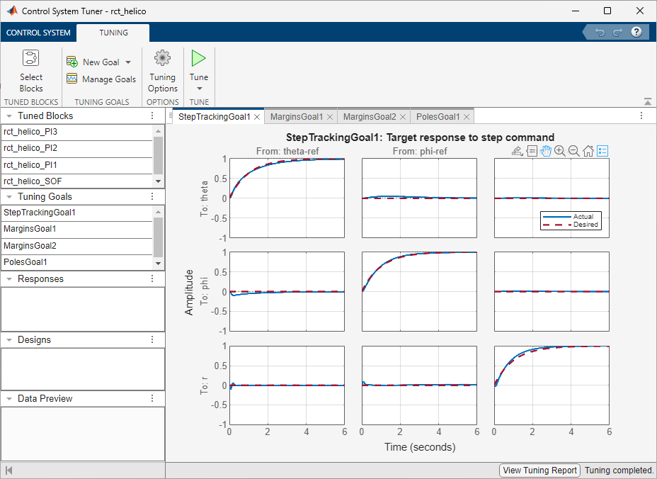
The blue line shows that the tuned response is very close to the target response, in pink. The rise time is about two seconds, and there is no overshoot and little cross-coupling.
Similarly, the MarginsGoal1 and MarginsGoal2 plots provide a visual assessment of the multivariable stability margins. (See the diskmargin reference page for more information about multivariable stability margins.) This plot shows that the stability margin is out of the shaded region, satisfying the requirement at all frequencies.

You can also view a numeric report of the tuning results. Click the Tuning Report at the bottom right of Control System Tuner.

When you tune the model, Control System Tuner converts each tuning goal to a function of the tunable parameters of the system and adjusts the parameters to minimize the value of those functions. For this example, the tuning report shows that the final values for all tuning goals are close to 1, which indicates that all the requirements are nearly met.
Validate the Tuned Design
In general, your Simulink model represents a nonlinear system. Control System Tuner linearizes the model at the operating point you specify in the app, and tunes parameters using the linear approximation of your system. Therefore, it is important to validate the controller design on the full Simulink model.
To do so, write the tuned parameter values back to the Simulink model. On the Control System tab, click Update Blocks. In the Simulink model window, simulate the model with the new parameter values. Observe the response to the step changes in setpoint commands, theta-ref, phi-ref, and r-ref at 0, 3, and 6 seconds respectively.
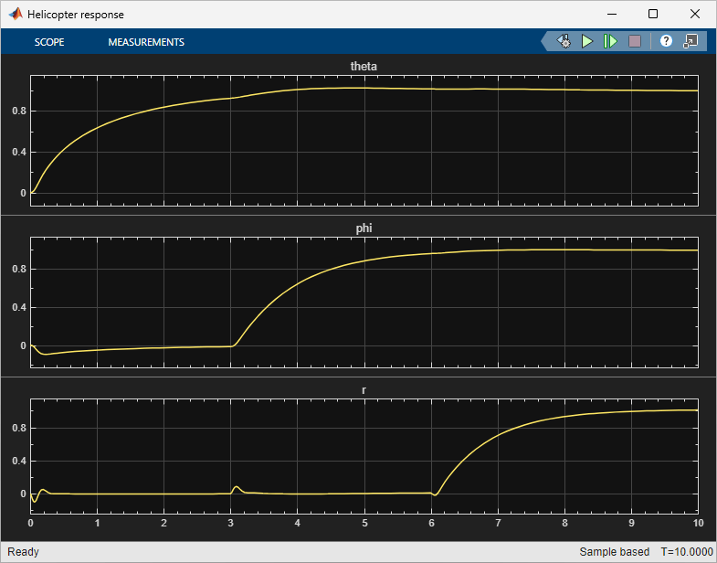
Examine the simulation to confirm that you get the desired responses in the Simulink model. Here, the rise time of each response is about 2 seconds with no overshoot, no steady-state error, and minimal cross-coupling, as specified in the design requirements.