Cascaded Multiloop Feedback Design
This example shows how to tune two cascaded feedback loops in Simulink® Control Design™ using Control System Designer.
This example designs controllers for two cascaded feedback loops in an airframe model such that the acceleration component (az) tracks reference signals with a maximum rise time of 0.5 seconds. The feedback loop structure in this example uses the body rate (q) as an inner feedback loop and the acceleration (az) as an outer feedback loop.
Open the airframe model.
open_system("scdairframectrl")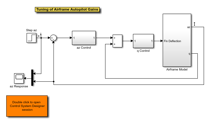
The two feedback controllers are:
scdairframectrl/q Control- A discrete-time integrator and a gain block stabilize the inner loop.
open_system("scdairframectrl/q Control")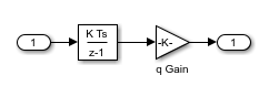
scdairframectrl/az Control- A discrete-time integrator, a discrete transfer function, and a gain block stabilize the outer loop.
open_system("scdairframectrl/az Control")
Decoupling Loops in Multiloop Systems
In Control System Designer, it is possible to design both the inner and outer loops of a cascaded system simultaneously. By default, when designing a multiloop feedback system, the coupling effects between loops are taken into account. However, when designing two feedback loops simultaneously, it can be necessary to decouple the feedback loops; that is, remove the effect of the outer loop when tuning the inner loop. This approach is the typical design procedure for designing cascaded feedback systems.
In this example, you design the inner feedback loop (q) with the effect of the outer loop (az) removed.
Configure Control System Designer
To design a controller using Control System Designer, you must:
Select the controller blocks that you want to tune.
Create the open-loop and closed-loop responses that you want to view.
For this example, you can:
Launch a preconfigured Control System Designer session by double-clicking the subsystem in the lower left corner of the model.
Configure Control System Designer using the following procedure.
To open Control System Designer, in the Simulink model, in the Apps gallery, click Control System Designer.
In the Edit Architecture dialog box, on the Blocks tab, click Add Blocks. In the Select Blocks to Tune dialog box, select the following blocks, and click OK.
scdairframectrl/q Control/q Gainscdairframectrl/az Control/az Gainscdairframectrl/az Control/az DTF
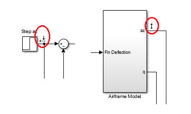
On the Signals tab, the analysis points defined in the Simulink model are automatically added as Locations.
Input:
scdairframectrl/Step az- Output port 1Output:
scdairframectrl/Airframe Model- Output port 1
To use the selected blocks and signals, click OK.
In Control System Designer, in the data browser, the Responses section contains the following open-loop responses, which Control System Designer automatically recognizes as potential feedback loops for open-loop design.
Output port 1 of
scdairframectrl/az Control/az DTFOutput port 1 of
scdairframectrl/az Control/az GainOutput port 1 of
scdairframectrl/q Control/q Gain
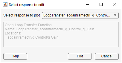
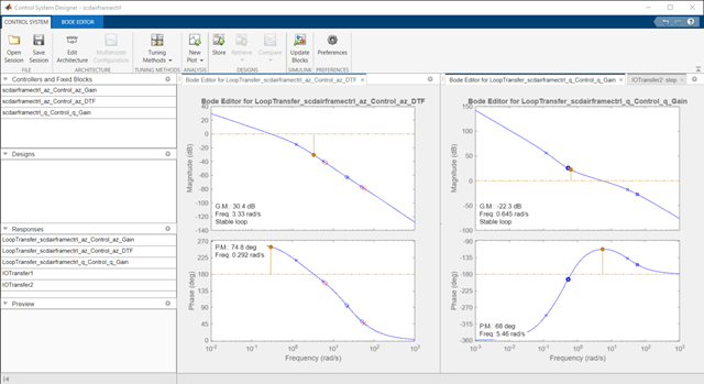
Open graphical Bode editors for each of the following responses. In Control System Designer, select Tuning Methods > Bode Editor. Then, in the Select response to edit dialog box, in the Select response to plot drop-down list, select the corresponding open-loop responses, and click Plot.
Open loop response at outport 1 of
scdairframectrl/az Control/az DTF

Open loop response at outport 1 of
scdairframectrl/q Control/q Gain
To view the closed-loop response of the feedback system, create a step plot for a new input-output transfer function response. Select New Plot > New Step. Then, in the New Step dialog box, in the Select response to plot drop-down list, select New input-output transfer response.
Add scdairframectrl/Step az/1 as an input signal and scdairframectrl/Airframe Model/1 as an output signal.

Click Plot.
Remove Effect of Outer Feedback Loop
In the outer-loop bode editor plot, Bode Editor for LoopTransfer_scdairframectrl_az_Control_az_DTF, increase the gain of the feedback loop by dragging the magnitude response upward. The inner-loop bode editor plot, Bode Editor for LoopTransfer_scdairframectrl_q_Control_q_Gain, also changes. This change is a result of the coupling between the feedback loops. A more systematic approach is to first design the inner feedback loop, with the outer loop open.
To remove the effect of the outer loop when designing the inner loop, add a loop opening to the open-loop response of the inner loop.
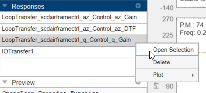
In the data browser, in the Responses area, right-click the inner loop response, and select Open Selection.
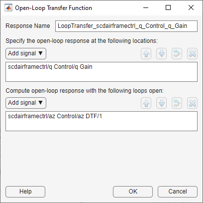
In the Open-Loop Transfer Function dialog box, specify scdairframectrl/az Control/az DTF/1 as the loop opening. Click OK.
In the outer-loop Bode editor plot, increase the gain by dragging the magnitude response. Since the loops are decoupled, the inner-loop Bode editor plot does not change.

You can now complete the design of the inner loop without the effect of the outer loop and simultaneously design the outer loop while taking the effect of the inner loop into account.
Tune Compensators
Control System Designer contains several methods tuning a control system:
Manually tune the parameters of each compensator using the compensator editor. For more information, see Tune Simulink Blocks Using Compensator Editor.
Graphically tune the compensator poles, zeros, and gains using open/closed-loop Bode, root locus, or Nichols editor plots. Click Tuning Methods, and select an editor under Graphical Tuning.
Optimize compensator parameters using both time-domain and frequency-domain design requirements (requires Simulink Design Optimization™ software). Click Tuning Methods, and select Optimization based tuning. For more information, see Enforcing Time and Frequency Requirements on a Single-Loop Controller Design (Simulink Design Optimization).
Compute initial compensator parameters using automated tuning based on parameters such as closed-loop time constants. Click Tuning Methods, and select either PID Tuning, Internal Model Control (IMC) Tuning, Loop Shaping (requires Robust Control Toolbox™ software), or LQG Design.
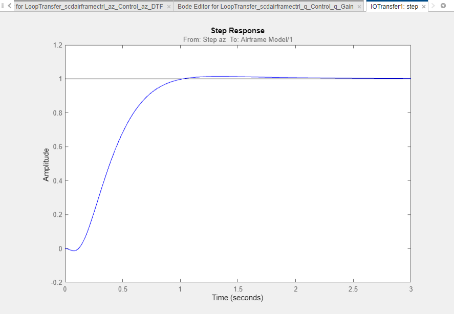
Complete Design
The following compensator parameters satisfy the design requirements:
scdairframectrl/q Control/q Gain:
K_q = 2.7717622
scdairframectrl/az Control/az Gain:
K_az = 0.00027507
scdairframectrl/az Control/az DTF:
      Numerator = [100.109745 -99.109745]
      Denominator = [1 -0.88893]
The response of the closed-loop system is shown in the following figure.
Update Simulink Model
To write the compensator parameters back to the Simulink model, click Update Blocks. You can then test your design on the nonlinear model.