블록 연결하기
모델에 있는 블록을 연결하여 블록 간의 관계를 설정합니다.
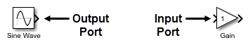
신호 선을 사용하여 대부분의 블록을 연결할 수 있습니다. 신호 선은 블록의 포트에 연결됩니다. 시뮬레이션 중에 신호는 출력 포트에서 연결된 입력 포트로 이동합니다.
신호 선을 분기함으로써 한 블록의 출력 포트에서 여러 블록의 입력 포트로 신호를 보낼 수 있습니다.
일부 블록에서는 블록의 입력 포트 개수를 변경할 수 있습니다. 예를 들어 여러 신호를 동일한 그래프에 플로팅하기 위해 Scope 블록의 입력 포트 개수를 늘릴 수 있습니다.
신호 선 레이아웃 변경에 대한 자세한 내용은 Configure Model Layout 항목을 참조하십시오. 신호 선에 레이블을 지정하는 방법에 대한 자세한 내용은 Configure Model Element Names and Labels 항목을 참조하십시오.
신호를 번들링하여 블록 다이어그램을 단순화할 수 있습니다. 신호 번들링에 대한 자세한 내용은 Group Signals or Messages into Virtual Buses 항목을 참조하십시오.
관련 블록은 신호 선 없이 연결됩니다. 관련 블록을 연결하는 방법에 대한 자세한 내용은 신호 선 없이 블록 연결하기 항목을 참조하십시오.
신호 선으로 블록 연결하기
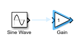
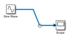
신호 선으로 2개의 블록을 연결하려면 한 블록의 출력 포트에서 포트 기호  를 클릭하고 다른 블록의 입력 포트에 끌어서 놓습니다.
다음과 같은 바로 가기를 사용하여 블록을 연결할 수 있습니다.
신호 선을 끌어서 놓지 않고 블록을 연결하려면 다음을 수행하십시오.
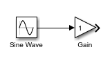
연결하려는 출력 포트와 입력 포트를 세로로 일렬로 정렬하고 그 사이에 다른 컴포넌트를 두지 않습니다. 이들 포트가 이미 일렬로 정렬되어 있는 경우에는 블록 중 하나를 이동하여 정렬을 끊었다가 다시 일렬로 정렬합니다. 포트를 정렬하기 위해 이동한 블록을 놓으면 해당 연결에 대한 미리보기가 표시됩니다.
연결을 만들기 위해 미리보기를 클릭합니다.
신호 선을 끌어서 놓지 않거나 포트를 일렬로 정렬하지 않고 블록을 연결하려면 다음을 수행하십시오.
연결하려는 출력 포트의 포트 기호를 클릭합니다. 연결할 수 있는 다른 컴포넌트의 입력 포트에 포트 힌트 기호
 가 표시됩니다.
해당 연결의 미리보기를 보려면 연결하려는 입력 포트의 포트 힌트 기호에 커서를 올려놓습니다.
연결을 만들기 위해 미리보기를 클릭합니다.

신호 선을 끌어서 놓지 않거나 포트를 일렬로 정렬하지 않고 여러 블록을 단일 블록에 연결하려면 다음을 수행하십시오.
연결하려는 출력 포트가 있는 블록을 선택합니다(예를 들어 블록 주위의 선택 상자를 마우스 왼쪽 버튼으로 클릭하고 끌어서 놓아 선택할 수 있음).
Ctrl 키를 누른 채로 연결하려는 입력 포트가 있는 블록을 클릭합니다.
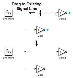
블록의 입력 포트와 출력 포트를 모두 기존 신호 선에 연결하려면 블록을 클릭하고 신호 선에 끌어서 놓습니다. 포트 기호
가 신호 선에 오도록 블록을 배치합니다. 출력 포트 기호가 사라지고 입력 포트 기호가 실선 화살표 머리로 바뀌면 포인터를 놓습니다.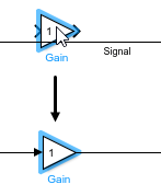
신호 선분을 대각선으로 만들려면 Shift 키를 누른 채로 또 다른 신호 선분에 연결되는 꼭짓점을 끌어서 놓습니다.
단일 출력 포트를 여러 입력 포트에 연결하기
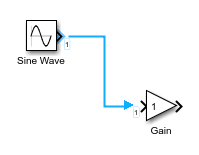
단일 출력 포트를 여러 입력 포트에 연결하려면, 한 입력 포트를 출력 포트에 연결한 다음 신호 선을 분기하여 다른 입력 포트에 연결합니다.
신호 선을 분기하려면 Ctrl 키를 누른 채로 기존 신호 선을 클릭하고 연결하려는 블록의 입력 포트에 끌어서 놓습니다.
팁
연결되지 않은 입력 포트의 포트 기호를 클릭하고 기존 신호 선에 끌어서 놓아 신호 선을 분기할 수도 있습니다.
여러 블록의 출력 포트를 단일 블록에 연결하기
일부 블록의 경우 입력 포트 쪽에 여러 개의 신호 선을 연결할 수 있습니다. 예를 들어 여러 신호를 하나의 그래프에 플로팅하기 위해 여러 블록의 출력 포트를 단일 Scope 블록에 연결할 수 있습니다.
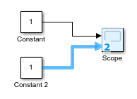
여러 블록의 출력 포트를 단일 블록에 연결하려면, 연결하려는 각 출력 포트에서 신호 선을 단일 블록의 입력 포트 쪽(왼쪽 모서리)에 끌어서 놓습니다. 블록 아이콘이 파란색으로 바뀌고 포트 번호가 표시되면 포인터를 놓습니다. 신호 선을 연결할 수 있는 입력 포트가 자동으로 생성됩니다.
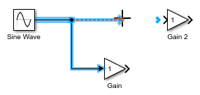
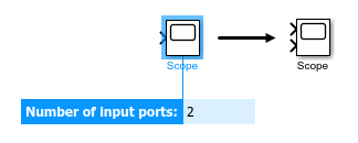
연결하려는 출력 포트를 가진 블록이 아직 모델에 없는 경우, 단일 블록의 입력 포트 개수를 늘리려면 다음을 수행하십시오.
플러스 기호가 포인터 옆에 나타날 때까지 블록의 입력 포트 쪽(왼쪽 모서리)에 커서를 올려놓습니다.

그런 다음 포인터를 클릭하고 블록의 바깥쪽으로 끌어서 놓습니다. 또 다른 블록의 출력 포트에 연결할 수 있는 파선 신호 선이 표시됩니다.

입력 포트를 삭제하려면 해당 포트 기호를 클릭하고 삭제를 누릅니다.
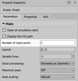
블록이 갖는 입력 포트 개수를 지정하려면 블록 파라미터 대화 상자 또는 속성 인스펙터의 파라미터 탭을 사용합니다.
팁
일부 블록의 경우 모델에 블록을 추가할 때 입력 포트 개수를 입력할 수 있습니다.
서브시스템 연결하기
서브시스템으로 신호를 보내려면, 서브시스템으로 보내려는 신호와 동일한 개수의 입력 포트가 서브시스템에 있어야 합니다.
서브시스템에서 신호를 받으려면, 서브시스템에서 받으려는 신호와 동일한 개수의 출력 포트가 서브시스템에 있어야 합니다.
빈 서브시스템을 모델에 추가하면 이러한 서브시스템에는 기본적으로 하나의 입력 포트와 하나의 출력 포트가 포함되어 있습니다.
서브시스템을 연결하려면 다음을 수행하십시오.
서브시스템에 들어가기 위해 Subsystem 블록을 더블 클릭합니다.

서브시스템 내에서, 필요한 개수의 입력 포트와 출력 포트를 추가합니다.
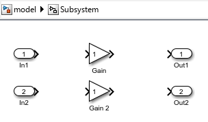
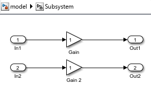
서브시스템 내에서, 입력 포트와 출력 포트를 서브시스템에 연결합니다.
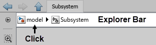
모델 계층 구조에서 한 레벨 위로 이동하려면 Simulink® 캔버스 상단에 있는 탐색 막대에서 Subsystem 블록 이름의 왼쪽에 있는 레벨 이름을 클릭합니다.
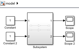
서브시스템으로 보내려는 신호의 신호 선을 Subsystem 블록의 입력 포트에 연결합니다.
Subsystem 블록의 각 입력 포트는 서브시스템 내의 Inport 블록에 대응됩니다. Subsystem 블록의 어떤 입력 포트가 서브시스템 내의 어떤 Inport 블록에 대응하는지를 포트 번호를 통해 알 수 있습니다.
서브시스템에서 받으려는 신호의 신호 선을 Subsystem 블록의 출력 포트에 연결합니다.
Subsystem 블록의 각 출력 포트는 서브시스템 내의 Outport 블록에 대응됩니다.
팁
수동으로 서브시스템을 연결하지 않으려면, Subsystem 블록을 추가하려는 모델 계층 구조의 레벨에서 서브시스템의 내용을 작성하십시오. 그런 다음, 다음과 같이 해당 내용을 서브시스템으로 변환하십시오.
캔버스에서 포인터를 클릭하고 끌어서 서브시스템 컴포넌트를 둘러싸는 직사각형을 그려 서브시스템 컴포넌트를 선택합니다.
줄임표가 나타나면 커서를 올려 놓습니다.
작업 모음이 펼쳐지면 서브시스템 만들기를 클릭합니다.
서브시스템으로 변환하면 자동으로 서브시스템 입력 포트와 출력 포트가 추가되고 연결됩니다.
포트 블록을 서브시스템에 연결하기
포트 블록을 Subsystem 블록에 연결하면 디폴트 포트 또는 요소 이름이 사용자 지정 포트 또는 요소 이름으로 대체됩니다.
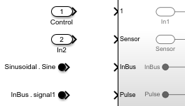
다음이 있다고 가정하겠습니다.
이름이
Control및In2인 Inport 블록Sinusoidal.Sine및InBus.signal1로 레이블이 지정된 In Bus Element 블록이름이
In1,Sensor,InBus및Pulse인 포트를 갖는 Subsystem 블록
Subsystem 블록 아이콘은 디폴트 이름이 In1인 Inport 블록의 포트 번호를 표시합니다.
포트를 연결하면 다음이 발생합니다.
사용자 지정 포트 이름이 그에 대응하는 디폴트 포트 이름을 대체합니다. 예를 들어, 이름이
Control인 Inport 블록을 레이블이1로 지정된 서브시스템 포트에 연결하면 서브시스템 포트 이름과 그에 대응하는 Inport 블록 이름이In1에서Control로 변경됩니다. 마찬가지로, 이름이In2인 Inport 블록을 이름이Sensor인 서브시스템 포트에 연결하면 Inport 블록 이름이In2에서Sensor로 변경됩니다.사용자 지정 요소 이름이 그에 대응하는 디폴트 포트 이름을 대체합니다. 예를 들어, 레이블이
Sinusoidal.Sine으로 지정된 In Bus Element 블록을 이름이InBus인 서브시스템 포트에 연결하면 서브시스템 포트 이름이InBus에서Sine으로 변경됩니다. (R2026a 이후)사용자 지정 포트 이름이 그에 대응하는 디폴트 요소 이름을 대체합니다. 예를 들어, 레이블이
InBus.signal1로 지정된 In Bus Element 블록을 이름이Pulse인 서브시스템 포트에 연결하면 In Bus Element 블록 요소 이름이signal1에서Pulse로 변경됩니다. (R2026a 이후)

참조된 모델을 불러온 경우 Model 블록 포트에 연결된 포트에도 동일한 동작이 적용됩니다. Model 블록 포트는 영향을 받지 않습니다.

신호 선 없이 블록 연결하기
관련 블록은 신호 선 없이 서로 연결됩니다.
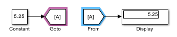
예를 들어 Goto 블록과 From 블록은 신호 선 없이 신호를 보내는 데 사용할 수 있는 관련 블록(related block)입니다. Goto 블록으로 들어오는 신호는 신호 선을 통과하지 않고 From 블록을 나갑니다.
관련 블록을 연결하려면 블록 파라미터 대화 상자 또는 속성 인스펙터의 파라미터 탭을 사용합니다.
팁
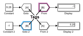
2개 이상의 관련 블록이 연결되어 있는지 확인하려면 그중에서 하나를 선택합니다. 선택한 블록에 연결된 모든 관련 블록이 자주색으로 강조 표시됩니다.
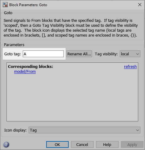
일부 관련 블록은 태그를 사용하여 연결됩니다. 예를 들어 동일한 태그를 가진 Goto 블록과 From 블록은 모두 연결됩니다.
블록 파라미터 대화 상자 또는 속성 인스펙터의 파라미터 탭에서 이러한 블록에 대한 태그를 설정할 수 있습니다.
Dashboard 라이브러리와 Customizable Blocks 라이브러리에 있는 블록도 관련 블록입니다. 이러한 라이브러리에 있는 Display 블록을 신호에 연결할 수 있습니다. Control 블록을 블록 파라미터 또는 변수에 연결할 수 있습니다. Dashboard 블록을 연결하는 방법에 대한 자세한 내용은 Connect Dashboard Blocks to Simulink Model 항목을 참조하십시오.
신호 선을 Goto 블록과 From 블록으로 변환하기 및 그 반대로 변환하기
긴 신호 선을 Goto 블록과 From 블록으로 대체하여 모델 다이어그램을 단순화할 수 있습니다. 그러나 신호 경로를 추적하려는 경우 신호 선을 확인하는 것이 유용할 수 있습니다.
신호 선과 가상 버스를 Goto와 From 블록 세트로 변환할 수 있고, Goto와 From 블록 세트를 신호 선으로 변환할 수 있습니다. Goto와 From 블록 세트는 연결된 하나의 Goto 블록과 From 블록의 그룹입니다. 즉, 이들 블록은 동일한 태그를 가집니다.
변환하려는 모델 요소는 다음 기준을 충족해야 합니다.
신호 선, 버스 또는 블록이 완전히 연결되어 있습니다.
신호 선, 버스 또는 블록이 모두 모델 계층 구조에서 동일한 위치에 있습니다. 즉, 모두가 계층 구조의 최상위 레벨에 있거나 모두가 동일한 컴포넌트에 있어야 합니다.
신호 선 또는 버스가 Goto 블록이나 From 블록에 연결되어 있지 않습니다.
변환 프로세스 중에 이러한 기준을 충족하지 않는 모델 요소는 무시됩니다. 블록 태그가 표시되는지 여부에 관계없이 변환을 수행할 수 있습니다.
Goto 블록과 신호 선에 연결되는 모든 From 블록을 변환하려면 Goto 블록을 선택합니다. From 블록과 신호 선에 연결되는 Goto 블록을 변환하려면 From 블록을 선택합니다. 선택한 블록 위에 표시되는 줄임표에 커서를 올려 놓습니다. 작업 메뉴가 펼쳐지면 신호로 변환을 선택합니다. 또는 Goto 블록이나 From 블록을 선택하고 Simulink 툴스트립의 Goto 탭 또는 From 탭에서 신호로 변환을 클릭합니다.
신호 선 또는 버스를 Goto와 From 블록 세트로 변환하려면 신호 선 또는 버스를 선택합니다. 줄임표가 나타나면 커서를 올려 놓습니다. 작업 메뉴가 펼쳐지면 Goto 블록 및 From 블록으로 변환을 선택합니다. 또는 신호 선이나 버스를 선택하고 툴스트립의 신호 탭에서 Goto/From으로 변환을 클릭합니다.
여러 Goto 블록과 연결된 모든 From 블록을 동시에 신호 선으로 변환하려면, Shift 키를 누른 채로 블록을 클릭하거나 블록 주위로 선택 상자를 끌어서 놓아 Goto 블록을 모두 선택합니다. Simulink 툴스트립의 Goto 탭에서 신호로 변환을 클릭합니다.
Goto 블록이 동일한 태그를 가진 여러 From 블록을 포함하고 있는 경우, From 블록의 서브셋을 신호 선으로 변환하려면, 변환하려는 From 블록을 선택합니다. 툴스트립의 From 탭에서 신호로 변환을 클릭합니다. 선택한 From 블록은 대응하는 Goto 블록에서 나오는 신호 선에 연결된 신호 선으로 변환됩니다. Goto 블록은 신호 선으로 변환되지 않습니다.
여러 신호 선 또는 버스를 동시에 Goto와 From 블록 세트로 변환하려면, Shift 키를 누른 채로 클릭하거나 선택 상자를 끌어서 놓아 신호 선 또는 버스를 선택합니다. 툴스트립의 신호 탭에서 Goto/From으로 변환을 클릭합니다.
블록을 주석 처리하거나 통과형 주석으로 처리하기
블록을 주석 처리(comment out)하거나 통과형 주석(comment through)으로 처리하면 모델에서 블록을 물리적으로 제거하지 않고도 시뮬레이션에서 블록을 제외시킬 수 있습니다.
주석 처리: 선택한 블록이 시뮬레이션에서 제외됩니다. 신호가 종단 처리되고 접지됩니다.
통과형 주석 처리: 선택한 블록이 시뮬레이션에서 제외됩니다. 신호가 통과됩니다. 통과형 주석으로 처리하려면 블록은 동일한 개수의 입력 포트와 출력 포트를 가져야 하며 제어 포트 또는 연결 포트가 없어야 합니다.
참고
다음 Simulink 블록을 주석 처리(comment out)하거나 통과형 주석(comment through)으로 처리하는 것은 지원되지 않습니다.
Inport
Outport
Connection Port
Argument Inport
Argument Outport
Data Store Memory
Goto Tag Visibility
Signal Generator 블록을 통과형 주석으로 처리하는 것은 지원되지 않습니다.
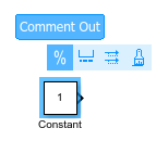
블록을 주석 처리하려면 블록을 선택합니다. 표시되는 작업 모음에서 주석 처리를 클릭합니다.
블록을 통과형 주석으로 처리하려면 블록을 마우스 오른쪽 버튼으로 클릭하고 통과형 주석 처리 버튼  을 클릭합니다.
팁
또는 블록을 선택하고 다음과 같이 누릅니다.
Ctrl+Shift+X: 주석 처리
Ctrl+Shift+Y: 통과형 주석 처리