Group Signals or Messages into Virtual Buses
To reduce line complexity and clutter in a block diagram and make incrementally changing an interface easier, use virtual buses. A virtual bus is analogous to a bundle of wires held together by tie wraps. For comparison, a nonvirtual bus is analogous to a structure in C code. You can access the bus as a whole or select specific elements from the bus.
When you create a virtual bus, group lines based on their functionality. By organizing signals or messages into logical groupings, you reduce the likelihood of significant refactoring.
Not all blocks can accept buses, and some blocks implicitly convert buses to vectors. To learn which blocks support which types of buses, see Bus-Capable Blocks. To identify bus conversions, see Identify Automatic Bus Conversions.
How you create virtual buses differs based on the location of the signals or messages that you want to group.
Within a component — Use Bus Creator blocks.
At the output interface of a component — Use Out Bus Element blocks.
At the input interface of a component — Use In Bus Element blocks.
To focus on fundamental steps, these examples are simple. However, buses are most useful when you have many signals or messages to group.
Tip
When you open a model or create a bus, the Simulink® Editor does not display bus line styles. To update the line styles, compile the model. In the Simulink Toolstrip, on the Modeling tab, click Update Model or Run.
To create buses at the input or output interface of a component using functions, see Programmatically Create Bus Element Ports.
Group Signal Lines Within Component
You can group signals into a virtual bus within a component by using Bus Creator blocks.
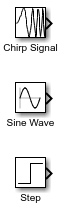
Open a new model and add three source blocks. For example, add a Chirp Signal, Sine Wave, and Step block.
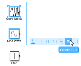
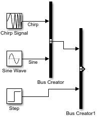
To create a bus that contains the outputs from multiple blocks, click and drag to select the blocks. For this example, select the Chirp Signal and Sine Wave blocks. In the action bar that appears, click Create Bus.
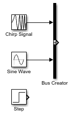
The software adds a Bus Creator block and connects the inputs to that block. The output of the Bus Creator block is a virtual bus.
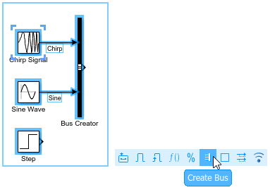
To make identifying the elements of the bus easier, label the inputs to the Bus Creator block.
Double-click the line between the Chirp Signal block and the Bus Creator block. Then, enter
Chirp.Double-click the line between the Sine Wave block and the Bus Creator block. Then, enter
Sine.
To create a second bus that contains the first bus and the output of the Step block, click and drag to select the Bus Creator and Step blocks. In the action bar that appears, click Create Bus. Including the Sine Wave and Chirp Signal blocks in your selection does not affect the result because these blocks provide elements of the input bus.
The software adds another Bus Creator block and connects the inputs to that block. The output of the Bus Creator block is a virtual bus that contains a nested bus.
You can nest buses to any depth. If one of the inputs to a Bus Creator block is a bus, then its output is a bus hierarchy that contains at least one nested bus.
Label the inputs to the new Bus Creator block.
Double-click the line between the Bus Creator blocks. Then, enter
Sinusoidal.Double-click the line between the Step block and the Bus Creator block. Then, enter
Step.
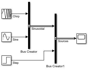
Optionally, arrange the blocks to improve the readability of the model.
Connect the output of the second Bus Creator block to a
Scope block and label the output Sources.
To visually identify the buses by line styles, in the Simulink Toolstrip, on the Modeling tab, click Update Model or Run.
Connect Multiple Output Signals to One Port
To group the outputs of a subsystem or model into a bus, use Out Bus Element blocks. Out Bus Element blocks accept signals, messages, and buses as input.
For example, create a simple model that connects three signals to one output port.
Open a new model and add a Chirp Signal, Sine Wave, and Step block.
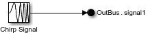
Add an Out Bus Element block to the model. Then, connect the Chirp Signal block to the Out Bus Element block.
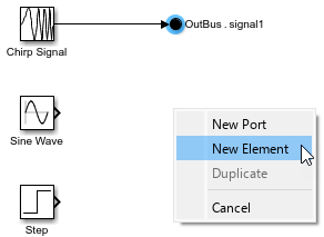
To make two copies of the Out Bus Element block, press Ctrl and drag the Out Bus Element block twice. To use the same port for the additional output signals, select New Element each time you copy the block.
Connect the Sine Wave and Step blocks to the Out Bus Element blocks.
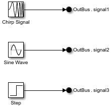
To make identifying the elements of a port easier, rename the elements. The label next to each Out Bus Element block has two parts. The first part of the label describes the port and uses the default name
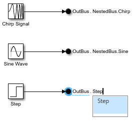
OutBus. The second part of the label describes a bus element and uses the default namesignal1. To create hierarchy by nesting a bus element in other buses, add a dot after each bus name.Double-click
signal1. Then, enterNestedBus.Chirp.Double-click
signal2. Then, enterNestedBus.Sine.Double-click
signal3. Then, enterStep.
The Out Bus Element blocks create a virtual bus at the output port of the model.
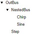
To inspect the bus hierarchy at the port, double-click one of the Out Bus
Element blocks. The dialog box displays a top-level bus named
OutBus that contains elements named
NestedBus and Step.
NestedBus contains elements named Chirp
and Sine.
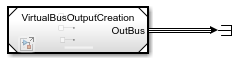
To see the virtual bus, reference the model in another model or move the Out Bus Element blocks into a subsystem. The line styles update when you compile the model. To compile the model, in the Simulink Toolstrip, on the Modeling tab, click Update Model or Run.
Optionally, add more elements to the bus hierarchy with or without adding more Out Bus Element blocks. For more information, see Define Output Bus Without Extra Blocks or Bus Objects.
Specify Multiple Input Signals at One Port
When a model or subsystem file expects an input bus, define the port with one or more In Bus Element blocks.
Suppose an input port expects a bus that contains a nested bus named
NestedBus and a signal named Step. The
nested bus contains signals named Chirp and
Sine. You expect to use only the signal named
Step and not the nested bus or its elements.
In a blank model or subsystem, add an In Bus Element block. This block creates an input port.

To rename the element that the block represents, in the block label, double-click
signal1. Then, replacesignal1withStep.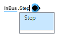
To define the rest of the bus hierarchy without additional In Bus
Element blocks and without a Simulink.Bus object, add
elements without adding blocks.
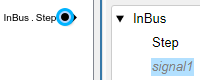
Open the Property Inspector. Then, select the In Bus Element block. Alternatively, double-click the block to open a dialog box.
In the Property Inspector or dialog box, select the top-level bus named
InBus. Then, click the down arrow button , and select Add element
without block.
, and select Add element
without block.
The new element is nested under the previously selected element. The block diagram is unchanged.
The new element name is gray and italicized to indicate that an In Bus Element block does not represent the element directly.
Double-click the new element name. Then, enter
NestedBus.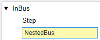
To add elements to the nested bus, select
NestedBus. Then, click the down arrow button, and select Add element
without block twice.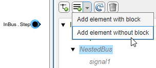
Before R2026a: To add multiple elements to a bus, select the parent before adding each element. The selection changes to the new element instead of remaining on the parent.
To rename the bus elements from
signalandsignal2toChirpandSine, respectively, double-click each element name and enter the new name.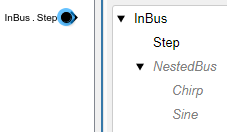
Tip
When you want to add many elements without blocks, using the
Simulink.Bus.addElementToPort function can be quicker
than using the dialog box. For an example, see Programmatically Create Bus Element Ports.
Add Blocks for Bus Element Ports
Suppose you want to add blocks for a bus element port.
To add blocks for input elements, click an element name, or hold
Ctrl as you click multiple element names. Then, click ![]() . For example, add blocks for
. For example, add blocks for
Chirp and Sine.
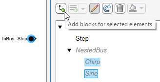
Corresponding In Bus Element blocks appear in the block diagram.
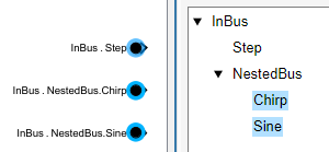
In the block label, each dot indicates a new level of hierarchy.
For output bus element ports, the way to add blocks for elements differs slightly.
To add blocks for output bus element ports, select an element that an existing
Out Bus Element block does not represent. Then, add an Out
Bus Element block by clicking ![]() . To prevent a conflict where multiple Out
Bus Element blocks represent the same element, you can add only one
Out Bus Element block at a time.
. To prevent a conflict where multiple Out
Bus Element blocks represent the same element, you can add only one
Out Bus Element block at a time.
For more examples and information, see In Bus Element and Out Bus Element.
Access Elements of Buses
You can access the bus as a whole or select specific signals, messages, or nested buses from the bus.
How you extract elements from a bus depends on the location of the bus.
Within a component — Use a Bus Selector block.
At a component interface — Use an In Bus Element block.
See Also
Bus Creator | Bus Selector | In Bus Element | Out Bus Element