Main Content

radarEmitter

Radar signals and interferences generator

Since R2021a

Description

The radarEmitter System object™ creates an emitter to simulate radar emissions. You can use the radarEmitter object in a scenario that detects and tracks moving and stationary platforms. Construct a scenario using radarScenario.

A radar emitter changes the look angle between updates by stepping the mechanical and electronic position of the beam in increments of the angular span specified in the FieldOfView property. The radar scans the total region in azimuth and elevation defined by the radar mechanical and electronic scan limits, MechanicalScanLimits and ElectronicScanLimits, respectively. If the scan limits for azimuth or elevation are set to [0 0], then no scanning is performed along that dimension for that scan mode. If the maximum mechanical scan rate for azimuth or elevation is set to zero, then no mechanical scanning is performed along that dimension.

To generate radar detections:

  1. Create the radarEmitter object and set its properties.

  2. Call the object with arguments, as if it were a function.

To learn more about how System objects work, see What Are System Objects?

Creation

Description

example

emitter = radarEmitter(EmitterIndex) creates a radar emitter object with default property values.

emitter = radarEmitter(EmitterIndex,'No scanning') is a convenience syntax that creates a radarEmitter that stares along the radar antenna boresight direction. No mechanical or electronic scanning is performed. This syntax sets the ScanMode property to 'No scanning'.

emitter = radarEmitter(EmitterIndex,'Raster') is a convenience syntax that creates a radarEmitter object that mechanically scans a raster pattern. The raster span is 90° in azimuth from –45° to +45° and in elevation from the horizon to 10° above the horizon. See Convenience Syntaxes for the properties set by this syntax.

emitter = radarEmitter(EmitterIndex,'Rotator') is a convenience syntax that creates a radarEmitter object that mechanically scans 360° in azimuth by mechanically rotating the antenna at a constant rate. When you set HasElevation to true, the radar antenna mechanically points towards the center of the elevation field of view. See Convenience Syntaxes for the properties set by this syntax.

example

emitter = radarEmitter(EmitterIndex,'Sector') is a convenience syntax to create a radarEmitter object that mechanically scans a 90° azimuth sector from –45° to +45°. Setting HasElevation to true, points the radar antenna towards the center of the elevation field of view. You can change the ScanMode to 'Electronic' to electronically scan the same azimuth sector. In this case, the antenna is not mechanically tilted in an electronic sector scan. Instead, beams are stacked electronically to process the entire elevation spanned by the scan limits in a single dwell. See Convenience Syntaxes for the properties set by this syntax.

emitter = radarEmitter(___,Name,Value) sets properties using one or more name-value pairs after all other input arguments. Enclose each property name in quotes. For example, radarEmitter('CenterFrequency',2e6) creates a radar emitter creates detections in the emitter Cartesian coordinate system and has a maximum detection range of 200 meters. If you specify the emitter index using the EmitterIndex property, you can omit the EmitterIndex input.

Properties

expand all

Unless otherwise indicated, properties are nontunable, which means you cannot change their values after calling the object. Objects lock when you call them, and the release function unlocks them.

If a property is tunable, you can change its value at any time.

For more information on changing property values, see System Design in MATLAB Using System Objects.

Unique emitter identifier, specified as a positive integer. When creating a radarEmitter system object, you must either specify the EmitterIndex as the first input argument in the creation syntax, or specify it as the value for the EmitterIndex property in the creation syntax.

Example: 2

Data Types: double

Emitter update rate, specified as a positive scalar. The emitter generates new emissions at intervals defined by the reciprocal of the UpdateRate property. This interval must be an integer multiple of the simulation time interval defined in radarScenario. Any update requested from the emitter between update intervals contains no emissions. Units are in hertz.

Example: 5

Data Types: double

Emitter location on platform, specified as a 1-by-3 real-valued vector. This property defines the coordinates of the emitter with respect to the platform origin. The default value specifies that the emitter origin is at the origin of its platform. Units are in meters.

Example: [.2 0.1 0]

Data Types: double

Orientation of the emitter with respect to the platform, specified as a three-element real-valued vector. Each element of the vector corresponds to an intrinsic Euler angle rotation that carries the body axes of the platform to the emitter axes. The three elements define the rotations around the z, y, and x axes respectively, in that order. The first rotation rotates the platform axes around the z-axis. The second rotation rotates the carried frame around the rotated y-axis. The final rotation rotates carried frame around the carried x-axis. Units are in degrees.

Example: [10 20 -15]

Data Types: double

Fields of view of sensor, specified as a 2-by-1 vector of positive scalars in degree, [azfov;elfov]. The field of view defines the total angular extent spanned by the sensor. The azimuth filed of view azfov must lie in the interval (0,360]. The elevation filed of view elfov must lie in the interval (0,180].

Example: [14;7]

Data Types: double

Scanning mode of radar, specified as 'Mechanical', 'Electronic', 'Mechanical and electronic', or 'No scanning'.

Scan Modes

ScanModePurpose
'Mechanical'The radar scans mechanically across the azimuth and elevation limits specified by the MechanicalScanLimits property. The scan direction increments by the radar field of view angle between dwells.
'Electronic'The radar scans electronically across the azimuth and elevation limits specified by the ElectronicScanLimits property. The scan direction increments by the radar field of view angle between dwells.
'Mechanical and electronic'The radar mechanically scans the antenna boresight across the mechanical scan limits and electronically scans beams relative to the antenna boresight across the electronic scan limits. The total field of regard scanned in this mode is the combination of the mechanical and electronic scan limits. The scan direction increments by the radar field of view angle between dwells.
'No scanning'The radar beam points along the antenna boresight defined by the mountingAngles property.

Example: 'No scanning'

Data Types: char

Maximum mechanical scan rate, specified as a nonnegative scalar or real-valued 2-by-1 vector with nonnegative entries.

When HasElevation is true, specify the scan rate as a 2-by-1 column vector of nonnegative entries,[maxAzRate; maxElRate]. maxAzRate is the maximum scan rate in azimuth and maxElRate is the maximum scan rate in elevation.

When HasElevation is false, specify the scan rate as a nonnegative scalar representing the maximum mechanical azimuth scan rate.

Scan rates set the maximum rate at which the radar can mechanically scan. The radar sets its scan rate to step the radar mechanical angle by the field of regard. If the required scan rate exceeds the maximum scan rate, the maximum scan rate is used. Units are degrees per second.

Example: [5,10]

Dependencies

To enable this property, set the ScanMode property to 'Mechanical' or 'Mechanical and electronic'.

Data Types: double

Angular limits of mechanical scan directions of radar, specified as a real-valued 1-by-2 row vector or a real-valued 2-by-2 matrix. The mechanical scan limits define the minimum and maximum mechanical angles the radar can scan from its mounted orientation.

When HasElevation is true, the scan limits take the form [minAz maxAz; minEl maxEl]. minAz and maxAz represent the minimum and maximum limits of the azimuth angle scan. minEl and maxEl represent the minimum and maximum limits of the elevation angle scan. When HasElevation is false, the scan limits take the form [minAz maxAz]. If you specify the scan limits as a 2-by-2 matrix but set HasElevation to false, the second row of the matrix is ignored.

Azimuthal scan limits cannot span more than 360° and elevation scan limits must lie within the closed interval [-90° 90°]. Units are in degrees.

Example: [-90 90;0 85]

Dependencies

To enable this property, set the ScanMode property to 'Mechanical' or 'Mechanical and electronic'.

Data Types: double

This property is read-only.

Current mechanical scan angle of radar, returned as a scalar or real-valued 2-by-1 vector. When HasElevation is true, the scan angle takes the form [Az;El]. Az and El represent the azimuth and elevation scan angles, respectively, relative to the mounted angle of the radar on the platform. When HasElevation is false, the scan angle is a scalar representing the azimuth scan angle.

Dependencies

To enable this property, set the ScanMode property to 'Mechanical' or 'Mechanical and electronic'.

Data Types: double

Angular limits of electronic scan directions of radar, specified as a real-valued 1-by-2 row vector or a real-valued 2-by-2 matrix. The electronic scan limits define the minimum and maximum electronic angles the radar can scan from its current mechanical direction.

When HasElevation is true, the scan limits take the form [minAz maxAz; minEl maxEl]. minAz and maxAz represent the minimum and maximum limits of the azimuth angle scan. minEl and maxEl represent the minimum and maximum limits of the elevation angle scan. When HasElevation is false, the scan limits take the form [minAz maxAz]. If you specify the scan limits as a 2-by-2 matrix but set HasElevation to false, the second row of the matrix is ignored.

Azimuthal scan limits and elevation scan limits must lie within the closed interval [-90° 90°]. Units are in degrees.

Example: [-90 90; 0 85]

Dependencies

To enable this property, set the ScanMode property to 'Electronic' or 'Mechanical and electronic'.

Data Types: double

This property is read-only.

Current electronic scan angle of radar, returned as a scalar or 1-by-2 column vector. When HasElevation is true, the scan angle takes the form [Az;El]. Az and El represent the azimuth and elevation scan angles, respectively. When HasElevation is false, the scan angle is a scalar representing the azimuth scan angle.

Dependencies

To enable this property, set the ScanMode property to 'Electronic' or 'Mechanical and electronic'.

Data Types: double

This property is read-only.

Look angle of emitter, specified as a scalar or real-valued 2-by-1 vector. Look angle is a combination of the mechanical angle and electronic angle depending on the ScanMode property. When HasElevation is true, the look angle takes the form [Az;El]. Az and El represent the azimuth and elevation look angles, respectively. When HasElevation is false, the look angle is a scalar representing the azimuth look angle.

ScanModeLookAngle
'Mechanical'MechnicalAngle
'Electronic'ElectronicAngle
'Mechanical and Electronic'MechnicalAngle + ElectronicAngle
'No scanning'0

Data Types: double

Enable the radar to measure target elevation angles and to scan in elevation, specified as false or true. Set this property to true to model a radar emitter that can estimate target elevation and scan in elevation.

Data Types: logical

Effective isotropic radiated power of the transmitter, specified as a scalar. EIRP is the root mean squared power input to a lossless isotropic antenna that gives the same power density in the far field as the actual transmitter. EIRP is equal to the power input to the transmitter antenna (in dBW) plus the transmitter isotropic antenna gain. Units are in dBi.

Data Types: double

Center frequency of radar band, specified as a positive scalar. Units are in hertz.

Example: 100e6

Data Types: double

Radar waveform bandwidth, specified as a positive scalar. Units are in hertz.

Example: 100e3

Data Types: double

Type of detected waveform, specified as a nonnegative integer.

Example: 1

Data Types: double

Processing gain when demodulating an emitted signal waveform, specified as a scalar. Processing gain is achieved by emitting a signal over a bandwidth which is greater than the minimum bandwidth necessary to send the information contained in the signal. Units are in dB.

Example: 20

Data Types: double

Usage

Description

example

radarsigs = emitter(platform,simTime) creates radar signals, radarsigs, from emitter on the platform at the current simulation time, simTime. The emitter object can simultaneously generate signals from multiple emitters on the platform.

[radarsigs,config] = emitter(platform,simTime) also returns the emitter configurations, config, at the current simulation time.

Input Arguments

expand all

Emitter platform, specified as a platform object, Platform, or a platform structure:

FieldDescription
PlatformID

Unique identifier for the platform, specified as a scalar positive integer. This is a required field which has no default value.

ClassID

User-defined integer used to classify the type of target, specified as a nonnegative integer. Zero is reserved for unclassified platform types and is the default value.

Position

Position of target in scenario coordinates, specified as a real-valued 1-by-3 vector. This is a required field. There is no default value. Units are in meters.

Velocity

Velocity of platform in scenario coordinates, specified as a real-valued 1-by-3 vector. Units are in meters per second. The default is [0 0 0].

Speed

Speed of the platform in the scenario frame specified as a real scalar. When speed is specified, the platform velocity is aligned with its orientation. Specify either the platform speed or velocity, but not both. Units are in meters per second The default is 0.

Acceleration

Acceleration of the platform in scenario coordinates specified as a 1-by-3 row vector in meters per second-squared. The default is [0 0 0].

Orientation

Orientation of the platform with respect to the local scenario NED coordinate frame, specified as a scalar quaternion or a 3-by-3 rotation matrix. Orientation defines the frame rotation from the local NED coordinate system to the current platform body coordinate system. Units are dimensionless. The default is quaternion(1,0,0,0).

AngularVelocity

Angular velocity of platform in scenario coordinates, specified as a real-valued 1-by-3 vector. The magnitude of the vector defines the angular speed. The direction defines the axis of clockwise rotation. Units are in degrees per second. The default is [0 0 0].

Signatures

Cell array of signatures defining the visibility of the platform to emitters and sensors in the scenario. The default is the cell {rcsSignature}.

Current simulation time, specified as a positive scalar. The radarScenario object calls the radar sensor at regular time intervals. The radar emitter generates new signals at intervals defined by the UpdateInterval property. The value of the UpdateInterval property must be an integer multiple of the simulation time interval. Updates requested from the emitter between update intervals contain no detections. Units are in seconds.

Example: 10.5

Data Types: double

Output Arguments

expand all

Radar emissions, returned as an array of radarEmission objects.

Current emitter configurations, returned as an array of structures.

FieldDescription
SensorIndex

Unique sensor index, returned as a positive integer.

IsValidTime

Valid detection time, returned as true or false. IsValidTime is false when detection updates are requested between update intervals specified by the update rate.

IsScanDone

IsScanDone is true when the sensor has completed a scan.

FieldOfView

Field of view of the sensor, returned as a 2-by-1 vector of positive real values, [azfov;elfov]. azfov and elfov represent the field of view in azimuth and elevation, respectively.

MeasurementParameters

Sensor measurement parameters, returned as an array of structures containing the coordinate frame transforms needed to transform positions and velocities in the top-level frame to the current sensor frame.

Data Types: struct

Object Functions

To use an object function, specify the System object as the first input argument. For example, to release system resources of a System object named obj, use this syntax:

release(obj)

expand all

coverageConfigSensor and emitter coverage configuration
perturbationsPerturbation defined on object
perturbApply perturbations to object
stepRun System object algorithm
releaseRelease resources and allow changes to System object property values and input characteristics
resetReset internal states of System object

Examples

collapse all

Create an emitter that stares from the front of a jammer.

Create a platform to mount the jammer on.

plat = struct( ...
    'PlatformID', 1, ...
    'Position', [0 0 0]);

Create an emitter that stares from the front of the jamming platform.

jammer = radarEmitter(1,'No scanning');

Emit the jamming waveform.

time = 0;
sig = jammer(plat, time)
sig = 
  radarEmission with properties:

              PlatformID: 1
            EmitterIndex: 1
          OriginPosition: [0 0 0]
          OriginVelocity: [0 0 0]
             Orientation: [1x1 quaternion]
             FieldOfView: [1 5]
         CenterFrequency: 300000000
               Bandwidth: 3000000
            WaveformType: 0
          ProcessingGain: 0
        PropagationRange: 0
    PropagationRangeRate: 0
                    EIRP: 100
                     RCS: 0

Model an radar emitter for an air traffic control tower.

Simulate one full rotation of the tower.

rpm = 12.5;
scanrate = rpm*360/60;
fov = [1.4;5];
updaterate = scanrate/fov(1);

Create a radarScenario object to manage the motion of the platforms.

scene = radarScenario('UpdateRate', updaterate, ...
    'StopTime', 60/rpm);

Add a platform to the scenario to host the air traffic control tower.

tower = platform(scene);

Create an emitter that provides 360 degree surveillance.

radarTx = radarEmitter(1,'Rotator', ...
    'UpdateRate',updaterate, ...
    'MountingLocation',[0 0 -15], ...
    'MaxMechanicalScanRate',scanrate, ...
    'FieldOfView',fov);

Attach the emitter to the tower.

tower.Emitters = radarTx
tower = 
  Platform with properties:

       PlatformID: 1
          ClassID: 0
         Position: [0 0 0]
      Orientation: [0 0 0]
       Dimensions: [1x1 struct]
       Trajectory: [1x1 kinematicTrajectory]
    PoseEstimator: [1x1 insSensor]
         Emitters: {[1x1 radarEmitter]}
          Sensors: {}
       Signatures: {[1x1 rcsSignature]}

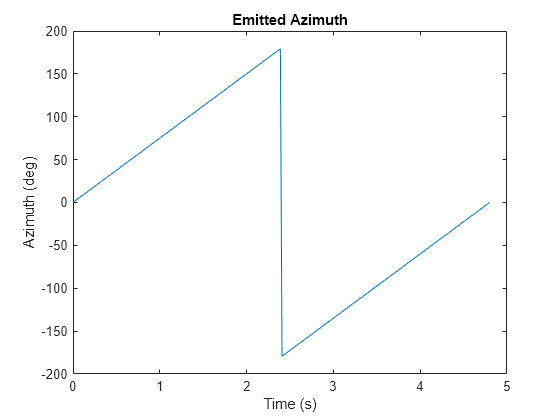
Rotate the antenna and emit the radar waveform.

loggedData = struct('Time', zeros(0,1), ...
    'Orientation', quaternion.zeros(0, 1));
while advance(scene)
    time = scene.SimulationTime;
    txSig = emit(tower, time); 
    loggedData.Time = [loggedData.Time; time];
    loggedData.Orientation = [loggedData.Orientation; ...
        txSig{1}.Orientation];
end

Plot the emitter azimuth direction.

angles = eulerd(loggedData.Orientation, 'zyx', 'frame');
plot(loggedData.Time, angles(:,1))
title('Emitted Azimuth')
xlabel('Time (s)')
ylabel('Azimuth (deg)')

Figure contains an axes object. The axes object with title Emitted Azimuth, xlabel Time (s), ylabel Azimuth (deg) contains an object of type line.

More About

expand all

Extended Capabilities

Version History

Introduced in R2021a