platform
Platform object belonging to radar scenario
Description
The platform function creates a
Platform object belonging to a radarScenario. You
can mount senors on a platform that detect or emit signals in the radar scenario. Specify the
platform signature as a radar cross section, target strength, or infrared intensity. You can
model platforms as points or cuboids by specifying the Dimensions
property and use the PoseEstimator property to determine the current
platform pose with respect to local scenario coordinates. You can create trajectories for any
platform using the kinematicTrajectory,
waypointTrajectory,
or geoTrajectory
System object™.
Use the detect, emit, and
receive functions
to collect detection, emissions, and receive I/Q signals for all senors mounted on the
platform, respectively. You can use pose to update the
pose for a platform. targetPoses
returns the poses of all targets in a scenario with respect to the observing platform.
Creation
Description
plat = platform(scenario)Platform object, plat, and adds the
platform to the radar scenario, scenario.
plat = platform(scenario,PropertyName=Value)Platform object, plat, with each
specified PropertyName set to the corresponding
Value. You can specify additional pairs of arguments in any order
as
PropertyName1=Value1,...,PropertyNameN=ValueN.
Properties
This property is read-only.
Scenario-defined platform identifier, specified as a positive integer. The scenario
automatically assigns PlatformID values to each platform, starting
with 1 for the first platform and incrementing by 1 for each new platform.
Data Types: double
Platform classification identifier, specified as a nonnegative integer. You can
define your own platform classification scheme and assign ClassID
values to platforms according to the scheme. The value of 0 is
reserved for an object of unknown or unassigned class.
Example: 5
Data Types: double | single
This property is read-only.
Current position of the platform, specified as a three-element numeric vector.
When the
IsEarthCenteredproperty of the scenario is set tofalse, the position is expressed as Cartesian coordinates [x,y,z] in meters.When the
IsEarthCenteredproperty of the scenario is set totrue, the position is expressed as geodetic coordinates [latitude,longitude,altitude], wherelatitudeandlongitudeare in degrees andaltitudeis in meters.
The position is determined by the platform trajectory defined in the
Trajectory property.
Data Types: double
This property is read-only.
Current orientation of the platform, specified as a three-element numeric vector in
degrees. The orientation is expressed as [yaw,
pitch, roll] rotation angles from the local
reference frame to the body frame of the platform. The orientation is determined by the
platform trajectory defined in the Trajectory property.
Data Types: double
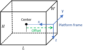
Platform dimensions and origin offset, specified as a structure. The structure contains the
Length, Width, Height, and
OriginOffset of a cuboid that approximates the dimensions of the
platform. The OriginOffset is the position vector from the center of
the cuboid to the origin of the platform coordinate frame. The
OriginOffset is expressed in the platform coordinate system. For
example, if the platform origin is at the center of the cuboid rear face as shown in the
figure, then set OriginOffset as [-L/2,
0, 0]. The default value for Dimensions is a structure
with all fields set to zero, which corresponds to a point model.
Fields of Dimensions
| Fields | Description | Default |
|---|---|---|
Length | Dimension of a cuboid along the x direction | 0 |
Width | Dimension of a cuboid along the y direction | 0 |
Height | Dimension of a cuboid along the z direction | 0 |
OriginOffset | Position of the platform coordinate frame origin with respect to the cuboid center | [0 0 0 ] |
Example: struct('Length',5,'Width',2.5,'Height',3.5,'OriginOffset',[-2.5 0 0])
For the
radarTransceiverplatformLength,Width, andHeightcan be set to any non-negative values when used in aradarScenario.For the
radarDataGenerator, platformLength,Width, andHeightare ignored if set to non-zero values in aradarScenario. All platforms are considered points.
Data Types: struct
Platform motion, specified as a kinematicTrajectory object, a waypointTrajectory object, or a geoTrajectory object. The
trajectory object defines the time evolution of the position and velocity of the
platform frame origin, as well as the orientation of the platform frame relative to the
scenario frame. The SampleRate property of the trajectory object
will automatically be set to the UpdateRate property of the
radarScenario and the SamplesPerFrame of the
trajectory object will be set to 1.
When the
IsEarthCenteredproperty of the scenario is set tofalse, use thekinematicTrajectoryor thewaypointTrajectoryobject. By default, the platform uses a stationarykinematicTrajectoryobject.When the
IsEarthCenteredproperty of the scenario is set totrue, use thegeoTrajectoryobject. By default, the platform uses a stationarygeoTrajectoryobject.
Platform signatures, specified as a cell array of signature objects or an empty cell
array ({}). The default value is a cell array containing an rcsSignature
object with default property values. If you have Sensor Fusion and Tracking Toolbox™, then the cell array can also include irSignature (Sensor Fusion and Tracking Toolbox)
and tsSignature (Sensor Fusion and Tracking Toolbox)
objects. The cell array contains at most one instance of each type of signature object.
A signature represents the reflection or emission pattern of a platform, such as its
radar cross-section, target strength, or IR intensity.
Platform pose estimator, specified as a pose-estimator object such as an insSensor
object. The pose estimator determines the platform pose with respect to the local NED
scenario coordinates. The interface of any pose estimator must match the interface of
the insSensor object. By default, the pose-estimator accuracy
properties are zero.
Emitters mounted on the platform, specified as a cell array of emitter objects such
as radarEmitter
objects. If you have Sensor Fusion and Tracking Toolbox, then the cell array can also include sonarEmitter (Sensor Fusion and Tracking Toolbox)
objects.
Sensors mounted on the platform, specified as a cell array of sensor objects such as
radarDataGenerator or radarTransceiver objects.
Object Functions
detect | Collect detections from all sensors mounted on platform |
emit | Collect emissions from all emitters mounted on platform |
pose | Update pose for platform |
receive | Receive I/Q signal from radars mounted on platform |
targetPoses | Target positions and orientations as seen from platform |
Examples
Create a radar scenario with two platforms that follow different trajectories.
sc = radarScenario('UpdateRate',100,'StopTime',1.2);
Create two platforms.
platfm1 = platform(sc);
platfm2 = platform(sc);
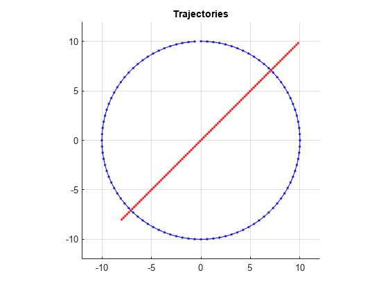
Platform 1 follows a circular path of radius 10 m for one second. This is accomplished by placing waypoints in a circular shape, ensuring that the first and last waypoint are the same.
wpts1 = [0 10 0; 10 0 0; 0 -10 0; -10 0 0; 0 10 0];
time1 = [0; 0.25; .5; .75; 1.0];
platfm1.Trajectory = waypointTrajectory(wpts1,time1);
Platform 2 follows a straight path for one second.
wpts2 = [-8 -8 0; 10 10 0];
time2 = [0; 1.0];
platfm2.Trajectory = waypointTrajectory(wpts2,time2);
Verify the number of platforms in the scenario.
disp(sc.Platforms)
{1×1 radar.scenario.Platform} {1×1 radar.scenario.Platform}
Run the simulation and plot the current position of each platform using an animated line.
figure
grid
axis equal
axis([-12 12 -12 12])
line1 = animatedline('DisplayName','Trajectory 1','Color','b','Marker','.');
line2 = animatedline('DisplayName','Trajectory 2','Color','r','Marker','.');
title('Trajectories')
p1 = pose(platfm1);
p2 = pose(platfm2);
addpoints(line1,p1.Position(1),p1.Position(2));
addpoints(line2,p2.Position(2),p2.Position(2));

while advance(sc)
    p1 = pose(platfm1);
    p2 = pose(platfm2);
    addpoints(line1,p1.Position(1),p1.Position(2));
    addpoints(line2,p2.Position(2),p2.Position(2));
    pause(0.1)
end
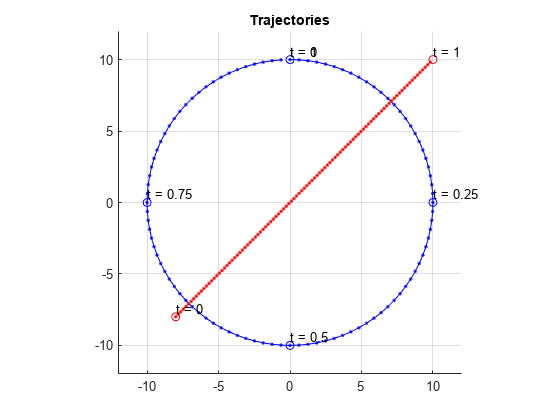
Plot the waypoints for both platforms.
hold on
plot(wpts1(:,1),wpts1(:,2),' ob')
text(wpts1(:,1),wpts1(:,2),"t = " + string(time1),'HorizontalAlignment','left','VerticalAlignment','bottom')
plot(wpts2(:,1),wpts2(:,2),' or')
text(wpts2(:,1),wpts2(:,2),"t = " + string(time2),'HorizontalAlignment','left','VerticalAlignment','bottom')
hold off
Create a radar scenario.
rs = radarScenario;
Create a platform with default property values and add it to the scenario.
plat = platform(rs);
Specify the trajectory of the platform as a circular path of radius 10 m for one second. This is accomplished by placing waypoints in a circular shape, ensuring that the first and last waypoint are the same.
wpts = [0 10 0; 10 0 0; 0 -10 0; -10 0 0; 0 10 0];
times = [0; 0.25; .5; .75; 1.0];
plat.Trajectory = waypointTrajectory(wpts,times);
Display the properties of the platform object.
plat
plat =
  Platform with properties:

       PlatformID: 1
          ClassID: 0
         Position: [0 10 0]
      Orientation: [-1.7180e-05 0 0]
       Dimensions: [1×1 struct]
       Trajectory: [1×1 waypointTrajectory]
    PoseEstimator: [1×1 insSensor]
         Emitters: {}
          Sensors: {}
       Signatures: {[1×1 rcsSignature]}
Perform the simulation, advancing one time step at a time. Display the simulation time and the position and velocity of the platform at each time step.
while advance(rs)
    p = pose(plat);
    disp(strcat("Time = ",num2str(rs.SimulationTime)))
    disp(strcat("  Position = [",num2str(p.Position),"]"))
    disp(strcat("  Velocity = [",num2str(p.Velocity),"]"))
end
Time = 0
Position = [0 10 0]
Velocity = [62.8318 -1.88403e-05 0]
Time = 0.1
Position = [5.8779 8.0902 0]
Velocity = [50.832 -36.9316 0]
Time = 0.2
Position = [9.5106 3.0902 0]
Velocity = [19.4161 -59.7566 0]
Time = 0.3
Position = [9.5106 -3.0902 0]
Velocity = [-19.4161 -59.7567 0]
Time = 0.4
Position = [5.8779 -8.0902 0]
Velocity = [-50.832 -36.9316 0]
Time = 0.5
Position = [0 -10 0]
Velocity = [-62.8319 1.88181e-05 0]
Time = 0.6
Position = [-5.8779 -8.0902 0]
Velocity = [-50.832 36.9316 0]
Time = 0.7
Position = [-9.5106 -3.0902 0]
Velocity = [-19.4161 59.7566 0]
Time = 0.8
Position = [-9.5106 3.0902 0]
Velocity = [19.4161 59.7566 0]
Time = 0.9
Position = [-5.8779 8.0902 0]
Velocity = [50.832 36.9316 0]
Time = 1
Position = [-7.10543e-15 10 0]
Velocity = [62.8319 -1.88404e-05 0]
Create a radar scenario.
rs = radarScenario;
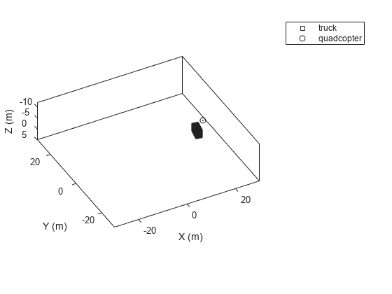
Create a cuboid platform for a truck with dimensions 5 m by 2.5 m by 3.5 m.
dim1 = struct('Length',5,'Width',2.5,'Height',3.5,'OriginOffset',[0 0 0]);
truck = platform(rs,'Dimension',dim1);
Specify the trajectory of the truck as a circle with radius 20 m.
truck.Trajectory = waypointTrajectory('Waypoints', ...
    [20*cos(2*pi*(0:10)'/10) 20*sin(2*pi*(0:10)'/10) -1.75*ones(11,1)], ...
    'TimeOfArrival',linspace(0,50,11)');
Create the platform for a small quadcopter with dimensions 0.3 m by 0.3 m by 0.1 m.
dim2 = struct('Length',.3,'Width',.3,'Height',.1,'OriginOffset',[0 0 0]);
quad = platform(rs,'Dimension',dim2);
Specify the trajectory of the quadcopter as a circle 10 m above the truck with a small angular delay. Note that the negative z coordinates correspond to positive elevation.
quad.Trajectory = waypointTrajectory('Waypoints', ...
    [20*cos(2*pi*((0:10)'-.6)/10) 20*sin(2*pi*((0:10)'-.6)/10) -11.80*ones(11,1)], ...
    'TimeOfArrival',linspace(0,50,11)');
Visualize the results using theaterPlot.
tp = theaterPlot('XLim',[-30 30],'YLim',[-30 30],'Zlim',[-12 5]);
pp1 = platformPlotter(tp,'DisplayName','truck','Marker','s');
pp2 = platformPlotter(tp,'DisplayName','quadcopter','Marker','o');
Specify a view direction and run the simulation.
view(-28,37);
set(gca,'Zdir','reverse');

while advance(rs)
    poses = platformPoses(rs);
    plotPlatform(pp1,poses(1).Position,truck.Dimensions,poses(1).Orientation);
    plotPlatform(pp2,poses(2).Position,quad.Dimensions,poses(2).Orientation);
end
Version History
Introduced in R2021a