전류 스케일링 서브시스템과 위치 스케일링 서브시스템 설계하기
다음 단계를 따라 전류 스케일링 서브시스템과 위치 스케일링 서브시스템을 설계합니다.
전류 스케일링 서브시스템을 만듭니다.

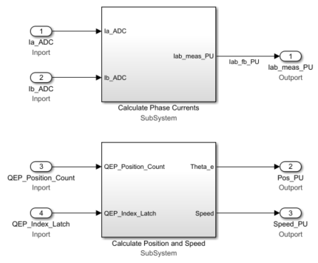
이 서브시스템은 ADC 카운트의 전류를 읽은 후 이를 PU(per-unit) 값으로 변환합니다.
이 서브시스템에서 IaOffset 및 IbOffset Data Store Memory 블록은 전류 측정값에 대한 ADC 오프셋이며 이는 하드웨어에 따라 달라집니다. 파일
mcb.getInverterParameters.m에는 몇몇 상용화된 인버터에 대한 디폴트 ADC 오프셋(CtSensAOffset 및 CtSensBOffset)이 포함되어 있습니다. 하드웨어의 ADC 오프셋 보정에 대한 자세한 내용은 개루프 제어에서 3상 AC 모터를 구동하고 ADC 오프셋 보정하기 항목을 참조하십시오.이 서브시스템에서는 ADC 카운트로 측정된 모터 상 전류가 PU 단위의 전류로 변환됩니다. 이 서브시스템에서
PU_System.I_base값은 베이스 전류를 나타냅니다. PU 단위계에 대한 자세한 내용은 Per-Unit System 항목을 참조하십시오.per-unit으로부터 실제 값을 계산하기 위해 베이스 값을 사용할 수 있습니다. 실제 값 또는 SI 단위 값을 구현하려면 예제 SI 단위를 사용한 PMSM의 자속 기준 제어에서 사용된 모델
mcb_pmsm_foc_qep_f28379d_SIUnit을 참조하십시오.IaOffset 및 IbOffset Data Store Memory 블록은 전류 서브시스템과 위치 서브시스템 간에 데이터를 공유하는 데 사용됩니다.
위치 스케일링 서브시스템을 만듭니다.

이 서브시스템은 QEP 펄스 카운트로부터 회전자 위치를 읽습니다.
이 서브시스템에서 Quadrature Decoder 블록은 플랜트 모델 또는 하드웨어 드라이버 블록에서 위치 카운트를 읽습니다. 이 블록은 인코더 위치 카운트에서 얻은 회전자의 기계적 위치를 PU 단위(
0~1)의 회전자 기계각으로 변환합니다.Mechanical to Electrical Position(Mech2Elec Position) 블록은 (블록 파라미터 대화 상자를 사용하거나 입력 포트를 통해 제공할 수 있는) QEP 오프셋에 맞춰 회전자 기계각을 조정한 다음 이를 전기각으로 변환합니다. FOC 알고리즘에서는 모터를 구동하기 위해 회전자 전기각이 필요합니다. QEP 인코더 오프셋을 계산하려면 Quadrature Encoder Offset Calibration for PMSM 항목을 참조하십시오.
Speed Measurement 블록은 회전자 위치로부터 속도를 계산합니다. Speed Measurement 블록 파라미터 대화 상자에서 속도 계산에 대한 지연(샘플 수) 파라미터를
20으로 설정하십시오. 이 워크플로에서는 현재 테스트 중인 모터의 최대 속도를 블록이 측정할 수 있도록 값20을 선택했습니다. Speed Measurement 블록은 속도를 PU 단위로 출력합니다.
결과로 생성된 두 서브시스템(Calculate Phase Currents 및 Calculate Position and Speed)은 전류 스케일링 로직과 위치 디코딩 로직을 포함합니다.
