이 번역 페이지는 최신 내용을 담고 있지 않습니다. 최신 내용을 영문으로 보려면 여기를 클릭하십시오.
액추에이터
R2026a등온 유체 도메인에서 액추에이션을 모델링하려면 다음 블록을 사용하십시오.
Simscape 블록
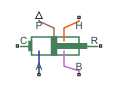 | Double-Acting Actuator (G-IL) | Linear actuator with isothermal liquid and gas chambers |
 | Double-Acting Rotary Actuator (IL) | Double-acting rotary actuator in an isothermal liquid system |
 | Double-Acting Actuator (IL) | Linear conversion of pressure differential to actuation in an isothermal liquid system |
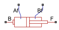 | Double-Acting Actuator (IL-PB) | Position-based double-acting actuator in isothermal liquid systems (R2026a 이후) |
 | Rotating Single-Acting Actuator (IL) | Actuator on a rotating shaft in an isothermal liquid network |
 | Single-Acting Rotary Actuator (IL) | Single-acting rotary actuator in an isothermal liquid system |
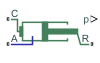 | Single-Acting Actuator (IL) | Single-acting linear actuator in an isothermal liquid system |
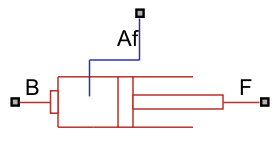 | Single-Acting Actuator (IL-PB) | Position-based single-acting linear actuator in isothermal liquid systems (R2026a 이후) |
추천 예제
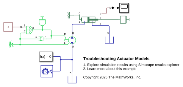
Troubleshoot Actuator Block Models
Troubleshoot problems in a model that contains actuator blocks and cannot converge during simulation. Blocks that interface with the mechanical domain, like actuators, can cause solver problems. These problems arise because the mechanical domain can introduce variables that cause a high differential index, which the solver cannot always overcome. A high differential index occurs when there are not sufficient degrees of freedom in the model. This behavior can cause issues where a model makes physical sense, but generates errors when the solver cannot converge.
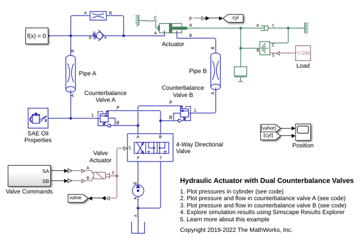
Hydraulic Actuator with Dual Counterbalance Valves
An actuator controlled by a 4-way directional valve and loaded with an overriding load, requiring the use of counterbalance valves to prevent the load from creeping when the directional valve is in the neutral position. In the neutral position, the directional valve connects ports A and B to the reservoir while blocking the pressure port P. The counterbalance valves block flow from returning to the reservoir, thus holding the actuator in place.
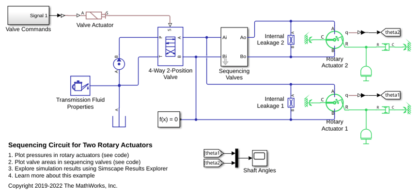
Sequencing Circuit for Two Rotary Actuators
A sequencing circuit that is based on four check valves installed in the pressure and return lines of the second rotary actuator. The cracking pressure of the meter-in check valves is set high enough to prevent flow into rotary actuator 2 while rotary actuator 1 is rotating, but lower than the pressure that develops once rotary actuator 1 reaches its hard stop. As a result, rotary actuator 2 starts moving only after rotary actuator 1 completes its stroke.
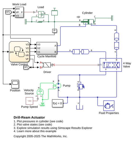
Drill-Ream Actuator
An actuator that drives a machine tool working unit performing a sequence of three technological operations: coarse drilling, fine drilling, and reaming. One of three pressure-compensated flow control valves controls the actuator speed as metering out return flow from the cylinder. Directional valves that are activated by a control unit perform the selection of an appropriate flow control.
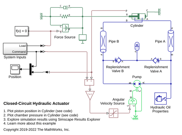
Closed-Circuit Hydraulic Actuator
A closed-circuit hydraulic actuator driven by a variable-speed pump. The actuator is arranged as a closed fluid system with two replenishment valves (check valves) and a spring-loaded accumulator serving as a replenishment reservoir. The pump speed is controlled by the difference between the commanded and measured piston position. The actuator acts against a spring, a damper, and a time-varying load.
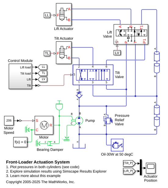
Front-Loader Actuation System
A simple actuation system that has a lift and tilt cylinder. Each cylinder is controlled by an open center, 6-way, 3-position directional valve. The valves are connected in series through their unloading branch such that the system pump unloads when both spool displacements are in neutral position. If either tilt or lift command applies, the unloading path closes.
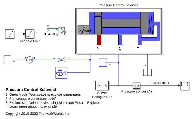
Pressure Control Solenoid
Model, parameterize, and test a pressure control solenoid valve. This example also generates a plot of the relationship between applied solenoid force and the resulting actuator port pressure.
Single-Stage Primary Cylinder
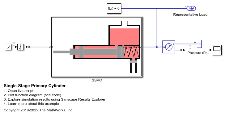
Model, parameterize, and test a single-stage primary cylinder, starting from manufacturer data sheet information. In this example, you calculate the unknown parameters given the numerical data extracted from the data sheet. After you simulate the model, you can compare the simulation push rod force versus pressure relationship curve with curve provided on the manufacturer data sheet.
Secondary Cylinder
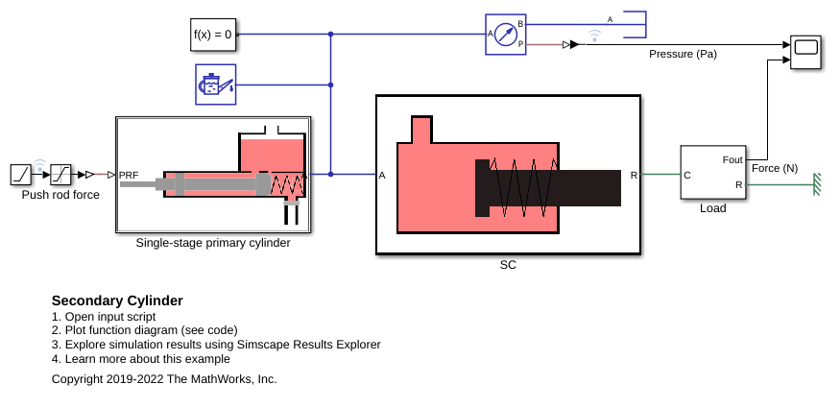
Model, parameterize and, test a secondary cylinder. Given the numerical data extracted from the datasheet of the single-stage primary cylinder, the unknown parameters of the secondary cylinder are calculated. The model is simulated to generate the plot between the applied force to the single-stage primary cylinder and the pressure developed inside the secondary cylinder.
Tandem Primary Cylinder
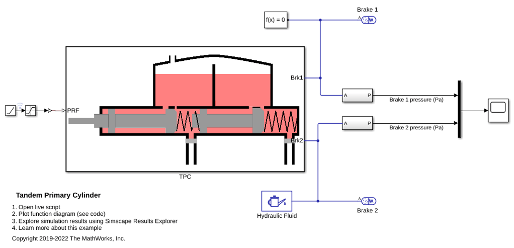
Model, parameterize and test a tandem primary cylinder starting from manufacturer data sheet information. Given the numerical data extracted from the data sheet, the example uses optimization to determine remaining unknown parameters. After you run the model you can compare the resulting push rod force - brake pressure relationship curve with the curve provided on the manufacturer data sheet.
Power-Assisted Steering Mechanism
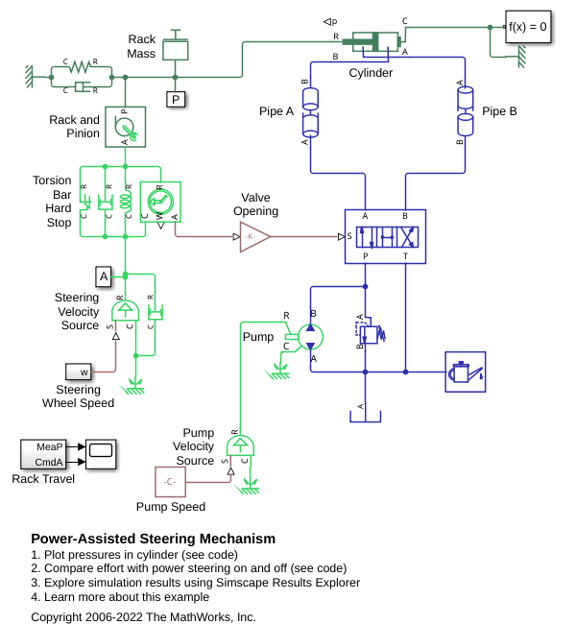
A simplified version of a power-assisted steering mechanism. The hydraulic actuation system includes a double-acting hydraulic cylinder, 4-way valve, fixed-displacement pump, and a pressure-relief valve. The steering rack acts against a load modeled by a spring and damper.
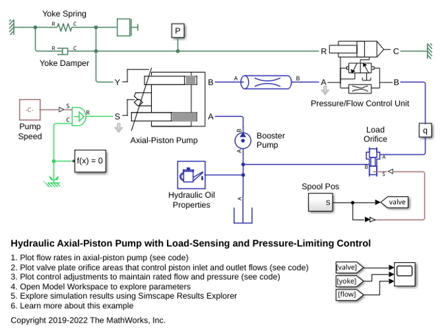
Hydraulic Axial-Piston Pump with Load-Sensing and Pressure-Limiting Control
A test rig designed to investigate the interaction between an axial-piston pump and a typical control unit simultaneously performing the load-sensing and pressure-limiting functions. To increase the fidelity of the simulation, this example uses a detailed model of the pump that accounts for the interaction between the pistons, swash plate, and valve plate.
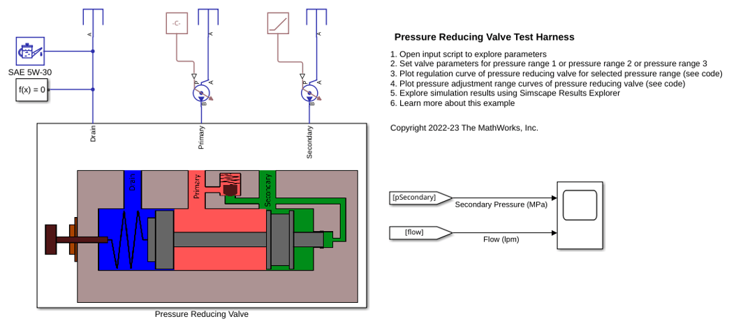
Pressure Reducing Valve Test Harness
Model, parameterize, and test a pressure reducing valve. The model is used to generate a plot of the regulation curve i.e. a plot of flow vs regulated pressure. This plot can be compared with the characteristics from the manufacturer datasheet to verify the test harness. The regulation curve displays two valve functions namely the reducing function and the relieving function. The reducing valve remains open when the pressure at the secondary port is less than a specified pressure, known as the set pressure. When the pressure at the secondary port meets or surpasses the set pressure, the reducing valve closes. In the regulation curve, the region of positive flow represents the phase when the reducing valve is open and gradually closes. The pressure reducing valve used in this example has a check valve that relieves pressure when the secondary pressure is about to surpass the set pressure. During this phase, the hydraulic fluid escapes via the check valve to the primary port keeping the secondary pressure constant at the set pressure. The region of negative flow in the regulation curve represents the phase when the pressure reducing valve is closed and the check valve opens gradually. Pressure reducing valves are used in industry to limit and maintain pressure during operations like hydraulic pressing, punching, drilling and stamping.

