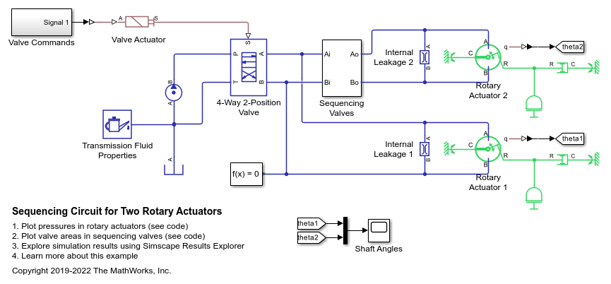
Sequencing Circuit for Two Rotary Actuators
This example shows a sequencing circuit that is based on four check valves installed in the pressure and return lines of the second rotary actuator. The cracking pressure of the meter-in check valves is set high enough to prevent flow into rotary actuator 2 while rotary actuator 1 is rotating, but lower than the pressure that develops once rotary actuator 1 reaches its hard stop. As a result, rotary actuator 2 starts moving only after rotary actuator 1 completes its stroke.
Model
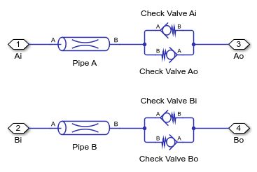
Sequencing Valves Subsystem
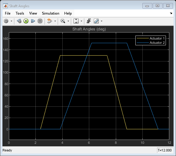
Simulation Results from Scopes
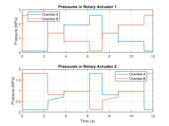
Simulation Results from Simscape Logging
This plot shows the sequence of pressures in the rotary actuator chambers. At the start of the simulation, both actuators are driven against their hard stops at 0 degree. At 2 seconds, the high pressure line is connected to chamber A of the actuators. The sequencing valves (check valves) prevent flow to rotary actuator 2 and maintain greater pressure in its chamber B over chamber A until rotary actuator 1 reaches its hard stop at 3.8 seconds. At that point, rotary actuator 1 is driven against its hard stop at maximum stroke and pressure builds up sufficiently to open the check valves. This lets flow into chamber A of rotary actuator 2 and causes it to rotate to its maximum stroke. At 7 seconds, the high pressure line switches and the opposite set of check valves repeat the sequence for the actuator rotation in the opposite direction.
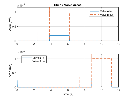
This plot shows the check valve areas that maintain the sequence of operations in the two rotary actuators. When rotary actuator 1 rotates, the meter-in check valve to chamber A of rotary actuator 2 remains closed until rotary actuator 1 completes its stroke. It then opens to enable flow into rotary actuator 2 so that it can rotate. The same sequence occurs when rotary actuator 1 rotates in the opposite direction.