insfilterErrorState
Estimate pose from IMU, GPS, and monocular visual odometry (MVO) data
Description
The insfilterErrorState object implements sensor fusion of IMU,
GPS, and monocular visual odometry (MVO) data to estimate pose in the NED (or ENU) reference
frame. The filter uses a 17-element state vector to track the orientation quaternion,
velocity, position, IMU sensor biases, and the MVO scaling factor. The
insfilterErrorState object uses an error-state Kalman filter to estimate
these quantities.
Creation
Syntax
Description
filter = insfilterErrorStateinsfilterErrorState object with default property values.
filter = insfilterErrorState('ReferenceFrame',RF)RF, of the
filter.
filter = insfilterErrorState(___,Name=Value)
Input Arguments
Properties
Object Functions
predict | Update states using accelerometer and gyroscope data for
insfilterErrorState |
correct | Correct states using direct state measurements for
insfilterErrorState |
residual | Residuals and residual covariances from direct state measurements for
insfilterErrorState |
fusegps | Correct states using GPS data for
insfilterErrorState |
residualgps | Residuals and residual covariance from GPS measurements for
insfilterErrorState |
fusemvo | Correct states using monocular visual odometry for
insfilterErrorState |
residualmvo | Residuals and residual covariance from monocular visual odometry measurements for
insfilterErrorState |
pose | Current orientation and position estimate for
insfilterErrorState |
reset | Reset internal states for insfilterErrorState |
stateinfo | Display state vector information for
insfilterErrorState |
tune | Tune insfilterErrorState parameters to reduce estimation
error |
copy | Create copy of insfilterErrorState |
Examples
Load logged data of a ground vehicle following a circular trajectory. The .mat file contains IMU and GPS sensor measurements and ground truth orientation and position.
load('loggedGroundVehicleCircle.mat', ...
    'imuFs','localOrigin', ...
    'initialStateCovariance', ...
    'accelData','gyroData', ...
    'gpsFs','gpsLLA','Rpos','gpsVel','Rvel', ...
    'trueOrient','truePos');
Create an INS filter to fuse IMU and GPS data using an error-state Kalman filter.
initialState = [compact(trueOrient(1)),truePos(1,:),-6.8e-3,2.5002,0,zeros(1,6),1].';
filt = insfilterErrorState;
filt.IMUSampleRate = imuFs;
filt.ReferenceLocation = localOrigin;
filt.State = initialState;
filt.StateCovariance = initialStateCovariance;
Preallocate variables for position and orientation. Allocate a variable for indexing into the GPS data.
numIMUSamples = size(accelData,1);
estOrient = ones(numIMUSamples,1,'quaternion');
estPos = zeros(numIMUSamples,3);

gpsIdx = 1;
Fuse accelerometer, gyroscope, and GPS data. The outer loop predicts the filter forward at the fastest sample rate (the IMU sample rate).
for idx = 1:numIMUSamples

    % Use predict to estimate the filter state based on the accelData and
    % gyroData arrays.
    predict(filt,accelData(idx,:),gyroData(idx,:));

    % GPS data is collected at a lower sample rate than IMU data. Fuse GPS
    % data at the lower rate.
    if mod(idx, imuFs / gpsFs) == 0
        % Correct the filter states based on the GPS data.
        fusegps(filt,gpsLLA(gpsIdx,:),Rpos,gpsVel(gpsIdx,:),Rvel);
        gpsIdx = gpsIdx + 1;
    end

    % Log the current pose estimate
    [estPos(idx,:), estOrient(idx,:)] = pose(filt);
end
Calculate the RMS errors between the known true position and orientation and the output from the error-state filter.
pErr = truePos - estPos;
qErr = rad2deg(dist(estOrient,trueOrient));

pRMS = sqrt(mean(pErr.^2));
qRMS = sqrt(mean(qErr.^2));

fprintf('Position RMS Error\n');
Position RMS Error
fprintf('\tX: %.2f, Y: %.2f, Z: %.2f (meters)\n\n',pRMS(1),pRMS(2),pRMS(3));X: 0.40, Y: 0.24, Z: 0.05 (meters)
fprintf('Quaternion Distance RMS Error\n');Quaternion Distance RMS Error
fprintf('\t%.2f (degrees)\n\n',qRMS);0.30 (degrees)
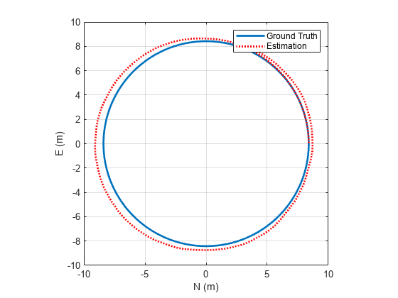
Visualize the true position and the estimated position.
plot(truePos(:,1),truePos(:,2),estPos(:,1),estPos(:,2),'r:','LineWidth',2)
grid on
axis square
xlabel('N (m)')
ylabel('E (m)')
legend('Ground Truth','Estimation')
Algorithms
Note: The following algorithm only applies to an NED reference frame.
insfilterErrorState uses a 17-axis error state Kalman filter structure to
estimate pose in the NED reference frame. The state is defined as:
where
q0, q1, q2, q3 –– Parts of orientation quaternion. The orientation quaternion represents a frame rotation from the platform's current orientation to the local NED coordinate system.
positionN, positionE, positionD –– Position of the platform in the local NED coordinate system.
gyrobiasX, gyrobiasY, gyrobiasZ –– Bias in the gyroscope reading.
accelbiasX, accelbiasY, accelbiasZ –– Bias in the accelerometer reading.
scaleFactor –– Scale factor of the pose estimate.
Given the conventional formulation of the state transition function,
the predicted state estimate is:
where
Δt –– IMU sample time.
gN, gE, gD –– Constant gravity vector in the NED frame.
Extended Capabilities
Version History
Introduced in R2019a
See Also
insfilterAsync | insfilterNonholonomic | insfilterMARG | insEKF