dsphdl.NCO
Generate real or complex sinusoidal signals
Description
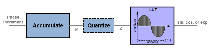
The NCO System object™ generates real or complex sinusoidal signals, while providing hardware-friendly control signals. A numerically-controlled oscillator (NCO) accumulates a phase increment and uses the quantized output of the accumulator as the index to a lookup table that contains the sine wave values. The wrap around of the fixed-point accumulator and quantizer data types provide periodicity of the sine wave, and quantization reduces the necessary size of the table for a given frequency resolution.
For an example of how to generate a sine wave using this System object, see Design a HDL-Compatible NCO Source. For more information on configuration and implementation, refer to the Algorithms section.
The NCO System object provides these features.
Optional frame-based output.
A lookup table compression option to reduce the lookup table size. This compression results in less than one LSB loss in precision. See Lookup Table Compression for more information.
An optional input argument for external dither.
An optional reset argument that resets the phase accumulator to its initial value.
An optional output argument for the current NCO phase.
To generate real or complex sinusoidal signals:
Create the
dsphdl.NCOobject and set its properties.Call the object with arguments, as if it were a function.
To learn more about how System objects work, see What Are System Objects?
Note
You can also generate HDL code for this hardware-optimized algorithm, without creating a MATLAB® script, by using the DSP HDL IP Designer app. The app provides the same interface and configuration options as the System object.
Creation
Syntax
Description
hdlnco = dsphdl.NCOhdlnco, that generates a real or complex sinusoidal
signal. The amplitude of the generated signal is always 1.
hdlnco = dsphdl.NCO(PropertyName=Value)
hdlnco = dsphdl.NCO(NumQuantizerAccumulatorBits=12, ...
AccumulatorWL=16);hdlnco = dsphdl.NCO(Inc,PhaseIncrementSource='Property')PhaseIncrement property set to
Inc, an integer scalar. To use the PhaseIncrement property, set the PhaseIncrementSource property to 'Property'. You can add
other name-value arguments before or after
PhaseIncrementSource.
Properties
Usage
Syntax
Description
The object returns the waveform value, Y, as a sine value, a cosine
value, a complex exponential value, or a [Sine,Cosine] pair of values,
depending on the Waveform
property.
[
returns a waveform, Y,ValidOut]
= hdlnco (ValidIn)Y, using waveform parameters from properties
rather than input arguments.
To use this syntax, set the PhaseIncrementSource, PhaseOffsetSource, and DitherSource
properties to 'Property'. These properties are independent of each
other. For example:
hdlnco = dsphdl.NCO(PhaseIncrementSource='Property', ...
       PhaseIncrement=phIncr,...
       PhaseOffset=phOffset,...
       NumDitherBits=4)
[
returns a waveform, Y,ValidOut]
= hdlnco(Inc,Offset,Dither,ValidIn)Y, with phase increment,
Inc, phase offset, Offset, and dither,
Dither.
This syntax applies when you set the PhaseIncrementSource, PhaseOffsetSource, and DitherSource
properties to 'Input port'. These properties are independent of each
other. You can mix and match the activation of these arguments.
PhaseIncrementSource is 'Input port' by default.
For example:
hdlnco = dsphdl.NCO(PhaseOffsetSource='Input port',...
                    DitherSource='Input port')
for k = 1:1/Ts
   y(k) = hdlnco(phIncr,phOffset,ditherBits,true);
end
[___] = hdlnco(___,
resets the accumulator value, but does not reset the output samples in the pipeline. If
ResetAccum,ValidIn)ValidIn is true, then the object continues to
generate the output waveform starting from the reset accumulator value.
To use this syntax, set the ResetAction
property to 1 (true). This syntax can include any of
the arguments from other syntaxes.
Input Arguments
Output Arguments
Object Functions
To use an object function, specify the
System object as the first input argument. For
example, to release system resources of a System object named obj, use
this syntax:
release(obj)
Examples
This example shows how to design an HDL-compatible NCO source.
Write a function that creates and calls the System object™, based on the waveform requirements. You can generate HDL from this function.
function yOut = HDLNCO510(validIn)
%HDLNCO510
% Generates one sample of NCO waveform using the dsphdl.NCO System object(TM)
% validIn is a logical scalar value
% phase increment, phase offset, and dither are fixed.
% You can generate HDL code from this function.

  persistent nco510;

  if isempty(nco510)
  % Since calculation of the object parameters results in constant values, this
  % code is not included in the generated HDL. The generated HDL code for
  % the NCO object is initialized with the constant property values.

   F0 = 510;     % Target output frequency in Hz
   dphi = pi/2;  % Target phase offset
   df = 0.05;    % Frequency resolution in Hz
   minSFDR = 96; % Spurious free dynamic range(SFDR) in dB
   Ts = 1/4000;  % Sample period in seconds

   % Calculate the number of accumulator bits required for the frequency
   % resolution and the number of quantized accumulator bits to satisfy the SFDR
   % requirement.
   Nacc = ceil(log2(1/(df*Ts)));
   % Actual frequency resolution achieved = 1/(Ts*2^Nacc)
   Nqacc = ceil((minSFDR-12)/6);
   % Calculate the phase increment and offset to achieve the target frequency
   % and offset.
   phIncr = round(F0*Ts*2^Nacc);
   phOffset = floor(2^Nacc*dphi/(2*pi));
   nco510 = dsphdl.NCO(PhaseIncrementSource='Property', ...
       PhaseIncrement=phIncr, ...
       PhaseOffset=phOffset, ...
       NumDitherBits=4, ...
       NumQuantizerAccumulatorBits=Nqacc, ...
       AccumulatorWL=Nacc);
  end

  yOut = nco510(validIn);

end
% Copyright 2012-2023 The MathWorks, Inc.
Call the object to generate data points in a sine wave. The input to the object is a valid control signal.
Ts = 1/4000;
y = zeros(1,1/Ts);
for k = 1:1/Ts
   y(k) = HDLNCO510(true);
end
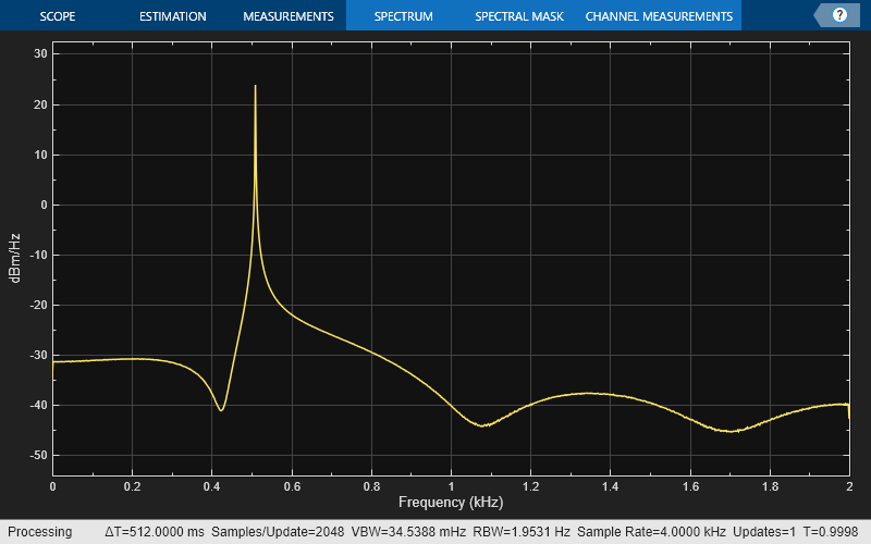
Plot the mean-square spectrum of the 510 Hz sine wave generated by the NCO.
sa = spectrumAnalyzer(SampleRate=1/Ts);
sa.SpectrumType = 'Power density';
sa.PlotAsTwoSidedSpectrum = false;
sa(y')
Algorithms
The frequency resolution of the sine wave depends on the size of the accumulator. Given a sample time, Ts, and the desired output frequency resolution Δf, calculate the necessary accumulator word length, N.
For a desired output frequency Fo, calculate the phase increment.
Quantizing the output of the phase accumulator enables you to reduce the lookup table size without lowering the frequency resolution. Calculate the quantized word length to achieve a desired spurious free dynamic range (SFDR).
Phase offset and dither are optionally added at the accumulator stage. For a desired phase offset (in radians) of the output waveform, calculate the phase offset value that the object adds in the accumulator.
The NCO implementation depends on whether you enable the LUTCompress
property.
Without lookup table compression, the object uses the same quarter-sine lookup table as
the dsp.NCO object. The size of the LUT is
2Q-2×W bits, where
Q is NumQuantizerAccumulatorBits and
W is OutputWL.
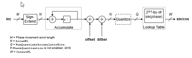
The object casts the phase increment value to match the accumulator word length.
If you do not enable PhaseQuantization, then
Q=N, where N is
AccumulatorWL. Consider the impact on simulator memory and hardware
resources when you select these parameters.
When you set the Waveform property to 'Complex
exponential' or 'Sine and cosine', the object implements a 1/8
sine wave lookup table for each of the sine and cosine parts of the waveform, and uses control
logic to select and invert the values to generate both sine and cosine waveforms. This
optimization means that dual output mode uses similar hardware resources compared to single
output mode.
For an example of how to generate a sine wave using this System object, see Design a HDL-Compatible NCO Source.
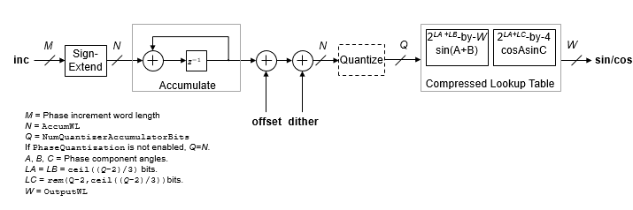
When you select lookup table (LUT) compression, the object applies the Sunderland compression method. Sunderland techniques use trigonometric identities to divide each phase of the quarter sine wave into three components and express it as:
If the quarter-sine phase has Q-2 bits, then the
phase components A and B have a word length of
LA=LB=ceil((Q-2)/3).
Phase component C contains the remaining phase bits. If the phase has 12
bits, then the quarter sine phase has 10 bits, and the components are defined as:
A, the four most significant bits
B, the next four bits
C, the remaining two least significant bits
Given the relative sizes of A, B, and C, the equation can be approximated by:
The object implements this equation with one LUT for and one LUT for . The second term is a fine correction factor that you can truncate to fewer bits without losing precision. Therefore, the second LUT returns a four-bit result.
With the default accumulator size of 16 bits, and the default quantized phase width of 12 bits, the LUTs use 28×16 plus 26×4 bits (4.5 kb). For comparison, a quarter-sine lookup table without compression uses 210×16 bits (16 kb). The compression approximation is accurate within one LSB, resulting in an SNR of at least 60 dB on the output. See [1].
When you set the Waveform property to 'Complex
exponential' or 'Sine and cosine', the object implements a
compressed lookup table for each of the sine and cosine parts of the waveform. The hardware
resource use is still smaller than dual output mode with an uncompressed table.
References
[1] Cordesses, L., "Direct Digital Synthesis: A Tool for Periodic Wave Generation (Part 1)." IEEE Signal Processing Magazine. Volume 21, Issue 4, July 2004, pp. 50–54.