Power Meter
Measure power and the CCDF of the power of voltage signal in Simulink
Libraries:
DSP System Toolbox /
Statistics
Communications Toolbox /
Utility Blocks
Description
The Power Meter block computes the power measurements of a voltage signal. When you select the Compute CCDF parameter, the block also calculates the complementary cumulative distribution function (CCDF) of the power of a voltage signal. The CCDF measurements that the block outputs are relative power and probability (in percentage). The power measurements include average power, peak power, and peak-to-average power ratio.
For more details on how the block computes the power measurements and the CCDF measurements, see Algorithms.
Examples
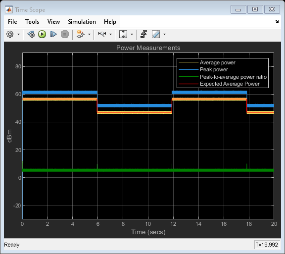
Compute Power Measurements of Voltage Signal in Simulink
Compute average power, peak power, and peak-to-average power ratio of voltage signal.
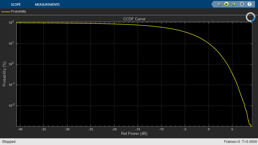
Compute CCDF Measurements of Voltage Signal in Simulink
Compute relative power and probability, and plot the CCDF curve in Array Plot.
Ports
Input
Specify the input signal in volts as a vector or a matrix. If
x is a matrix, the block treats each column as an independent
channel and computes the power measurement along each channel.
When the Allow arbitrary frame length for fixed-size input signals parameter appears and is not selected, and you input a fixed-size signal, the frame length must be a multiple of the hop size (window length − overlap length). In all other cases, the input frame length can be arbitrary.
The block accepts variable-size inputs (frame length changes during simulation). When you input a variable-size signal, the frame length of the signal can be arbitrary.
Data Types: single | double
Complex Number Support: Yes
Specify the boolean reset signal as a scalar. If the input on the
Rst port is true, the block clears the
internal histograms and statistics before processing the current input. If the input
on the Rst port is false, the block computes
the measurements from the start of the simulation or from the last reset.
Dependencies
To enable this port, select the Compute CCDF and Reset port parameters.
Data Types: Boolean
Output
Average power of the voltage signal from the start of the simulation or from the last reset, returned as a scalar, vector, or a matrix. The block computes the average power along each channel in the units specified in the Output power units parameter. For details on how the block computes the average power, see Average Power.
If you clear the Compute CCDF parameter, the block computes the moving average power using the Sliding Window Method.
See this table for details on the output signal dimensions.
| Input Signal | Input Dimensions | Output Dimensions When Allow arbitrary frame length for fixed-size input signals Appears | Output Dimensions When Allow arbitrary frame length for fixed-size input signals Does Not Appear |
|---|---|---|---|
| Fixed-size signal | P-by-M, where M is a multiple of the hop size (window length − overlap length) | (P/hop size)-by-M | P-by-M |
| Fixed-size signal | P-by-M, where M is not a multiple of the hop size (window length − overlap length) |
If you do not select Allow arbitrary frame length for fixed-size input signals, the block errors. | P-by-M |
| Variable-size signal | P-by-M | ceil(P/hop
size)-by-M | P-by-M |
When the output has an upper bound size of
ceil(P/hop size)-by-M,
during simulation, the size of the first dimension varies within this bound, while the
size of the second dimension remains constant.
If you select the Compute CCDF parameter, the block computes the stationary average power of the entire signal along each channel. In this case, the size of the output is 1-by-M, where M is the number of channels (columns) in the input signal.
Dependencies
To enable this port, set Measurement to
Average power or All.
Data Types: single | double
Peak power of the voltage signal from the start of the simulation or from the last reset, returned as a scalar, vector, or a matrix. The block computes the peak power along each channel in the units specified in the Output power units parameter. For details on how the block computes the peak power, see Peak Power.
If you clear the Compute CCDF parameter, the block computes the moving peak power using the Sliding Window Method.
See this table for details on the output signal dimensions.
| Input Signal | Input Dimensions | Output Dimensions When Allow arbitrary frame length for fixed-size input signals Appears | Output Dimensions When Allow arbitrary frame length for fixed-size input signals Does Not Appear |
|---|---|---|---|
| Fixed-size signal | P-by-M, where M is a multiple of the hop size (window length − overlap length) | (P/hop size)-by-M | P-by-M |
| Fixed-size signal | P-by-M, where M is not a multiple of the hop size (window length − overlap length) |
If you do not select Allow arbitrary frame length for fixed-size input signals, the block errors. | P-by-M |
| Variable-size signal | P-by-M | ceil(P/hop
size)-by-M | P-by-M |
When the output has an upper bound size of
ceil(P/hop size)-by-M,
during simulation, the size of the first dimension varies within this bound, while the
size of the second dimension remains constant.
If you select the Compute CCDF parameter, the block computes the stationary peak power of the entire signal along each channel. In this case, the size of the output is 1-by-M, where M is the number of channels (columns) in the input signal.
Dependencies
To enable this port, set Measurement to Peak
power or All.
Data Types: single | double
Ratio of the peak power to the average power (PAPR) of the voltage signal, returned as a scalar, vector, or a matrix. The block computes the peak-to-average power ratio along each channel. For details on how the block computes this measurement, see Peak-to-Average Power Ratio.
If you clear the Compute CCDF parameter, the block computes the moving peak-to-average power ratio using the Sliding Window Method.
See this table for details on the output signal dimensions.
| Input Signal | Input Dimensions | Output Dimensions When Allow arbitrary frame length for fixed-size input signals Appears | Output Dimensions When Allow arbitrary frame length for fixed-size input signals Does Not Appear |
|---|---|---|---|
| Fixed-size signal | P-by-M, where M is a multiple of the hop size (window length − overlap length) | (P/hop size)-by-M | P-by-M |
| Fixed-size signal | P-by-M, where M is not a multiple of the hop size (window length − overlap length) |
If you do not select Allow arbitrary frame length for fixed-size input signals, the block errors. | P-by-M |
| Variable-size signal | P-by-M | ceil(P/hop
size)-by-M | P-by-M |
When the output has an upper bound size of
ceil(P/hop size)-by-M,
during simulation, the size of the first dimension varies within this bound, while the
size of the second dimension remains constant.
If you select the Compute CCDF parameter, the block computes the stationary peak-to-average power ratio of the entire signal along each channel. In this case, the size of the output is 1-by-M, where M is the number of channels (columns) in the input signal.
PAPR should be less that 100 dB to obtain accurate CCDF measurements. If PAPR is above 100 dB, the block shows only the highest 100 dB power levels.
Dependencies
To enable this port, set Measurement to
Peak-to-average power ratio or
All.
Data Types: single | double
Relative power
                      (dB above average power)
, returned as an N-by-M matrix, where:
M is the number of channels (columns) in the input signal.
When you set CCDF output to
Relative power (dB above average power), N equals the length of the column vector that you specify in the Specify probability (%) for relative power output parameter.When you set CCDF output to
Relative power
                      and probability (whole CCDF curve)
, N equalsceil(Power range (dB)/Power resolution (dB)) + 1.
Relative power is the power in dB by which the instantaneous signal power is above the average signal power with a probability of Prob, expressed as a percentage. For details on how the block computes relative power, see Relative Power.
Dependencies
To enable this port, select the Compute CCDF parameter and
then set the CCDF output parameter to Relative
power (dB above average power) or Relative power and
probability (whole CCDF curve).
Data Types: single | double
Probability in percentage, returned as an N-by-M matrix, where:
M is the number of channels (columns) in the input signal.
When you set CCDF output to
Probability (%), N equals the length of the column vector that you specify in the Specify relative power (dB) for probability output parameter.When you set CCDF output to
Relative power and probability (whole CCDF curve), N equalsceil(Power range (dB)/Power resolution (dB)) + 1.
Prob(i)/100 is the probability that the instantaneous signal power of the jth channel is above its average signal power by RelPwr(i,j) in dB.
Dependencies
To enable this port, select the Compute CCDF parameter and
then set the CCDF output parameter to Probability
(%) or Relative power and probability (whole CCDF
curve).
Data Types: single | double
Parameters
Specify the desired power measurement as one of the following:
Average power(default)Peak powerPeak-to-average power ratioAll
For details on how the block computes these measurements, see Algorithms.
Specify the reference load that the power meter uses to compute power values as a real, positive scalar in ohms.
Tunable: Yes
Data Types: single | double
Specify the units of the measured power values as one of the following:
dBmdBWWatts
Select the Compute CCDF parameter to enable the block to compute the CCDF of the power of voltage signals. CCDF measurements include the relative power and the probability (in percentage). Relative power is the amount of power in dB by which the instantaneous signal power is above the average signal power. Probability in percentage refers to the probability that the instantaneous signal power is above the average signal power by the relative power in dB.
These measurements provide a qualitative way to view the power distribution between the amplitude values of an input signal over time. The CCDF curves (plot of probability in percentage against relative power in dB) are useful indicators of the dynamic range of a signal.
When you select Compute CCDF:
The block uses all the input samples from the start of the simulation or from a reset signal on the Rst port to compute the statistics. The power measurements are stationary.
You can specify variable-size input signals.
When you clear Compute CCDF,
The block does not calculate the CCDF measurements and computes the power measurements using the Sliding Window Method.
The block accepts input signals of arbitrary frame length only when you select the Allow arbitrary frame length for fixed-size input signals parameter.
Specify the window length over which the block computes the measurement as a positive integer.
Dependencies
To enable this parameter, clear the Compute CCDF check box.
When you select Compute CCDF, Window length
becomes Inf.
Data Types: single | double
Specify the overlap length between sliding windows as a nonnegative integer. The value of overlap length varies in the range [0, Window length − 1].
Dependencies
To enable this parameter, clear the Compute CCDF check box.
When you select Compute CCDF, Overlap length
becomes 0.
Data Types: single | double
Specify whether fixed-size input signals (whose size does not change during simulation) can have an arbitrary frame length, where the frame length does not have to be multiple of the hop size. Hop size is defined as Window length − Overlap length. The block uses this parameter setting only for fixed-size input signals and ignores this parameter if the input has a variable-size.
When the input signal is a variable-size signal, the signal can have arbitrary frame length, that is, the frame length does not have to be a multiple of the hop size.
For fixed-size input signals, if you:
Select the Allow arbitrary frame length for fixed-size input signals parameter, the frame length of the signal does not have to be a multiple of the hop size. If the input is not a multiple of the hop size, then the output is generally a variable-size signal. Therefore, to support arbitrary input size, the block must also support variable-size operations, which you can enable by selecting the Allow arbitrary frame length for fixed-size input signals parameter.
Clear the Allow arbitrary frame length for fixed-size input signals parameter, the input frame length must be a multiple of the hop size.
Dependencies
To enable this parameter, clear the Compute CCDF parameter.
Specify the x-axis range of the CCDF curves as a positive scalar in dB. The CCDF curves end at the maximum relative power, namely, the PAPR of the signal, and start at PAPR − Power range (dB). In the CCDF capability of the Power Meter block, relative power is the power in dB by which the instantaneous signal power is above the average signal power.
Dependencies
To enable this parameter, select the Compute CCDF check box.
Data Types: single | double
Specify the x-axis resolution of the CCDF curves as a positive scalar in dB.
Dependencies
To enable this parameter, select the Compute CCDF check box.
Data Types: single | double
Specify the block to output:
RelPwr — Relative power (dB above average power). This is the amount of power in dB by which the instantaneous signal power is above the average power.
Prob — Probability in percentage. This is the probability that the instantaneous signal power is above the average signal power by the value of the relative power in dB.
Both the RelPwr and the Prob.
Dependencies
To enable this parameter, select the Compute CCDF check box.
Specify the probability (in percentage) for the relative power output as a column vector. The length of this vector determines the number of rows in the relative power output at the RelPwr port.
Dependencies
To enable this parameter, select the Compute CCDF check box
and set the CCDF output parameter to Relative power
(dB above average power).
This also enables the RelPwr output port.
Data Types: single | double
Specify the relative power (in dB) for the probability output as a column vector. The length of this vector determines the number of rows in the probability output at the Prob port.
Dependencies
To enable this parameter, select the Compute CCDF check box
and set the CCDF output parameter to Probability
(%).
This also enables the Prob output port.
Data Types: single | double
Select this parameter to enable the input port Rst that accepts
a boolean signal. If the value at the Rst port is
true, then the block clears the internal histograms and statistics
before processing the current input.
Dependencies
To enable this parameter, select the Compute CCDF check box.
Specify the type of simulation to run. You can set this parameter to:
Interpreted execution— Simulate model using the MATLAB® interpreter. This option shortens startup time.Code generation— Simulate model using generated C code. The first time you run a simulation, Simulink® generates C code for the block. The C code is reused for subsequent simulations as long as the model does not change. This option requires additional startup time but provides faster subsequent simulations.
Block Characteristics
Data Types |
|
Direct Feedthrough |
|
Multidimensional Signals |
|
Variable-Size Signals |
|
Zero-Crossing Detection |
|
Algorithms
When you do not configure the power meter to compute the CCDF measurements, the power meter computes the moving power measurements using the sliding window method.
In the sliding window method, the block computes the power measurement over a finite duration of the signal. The window length defines the length of the data over which the algorithm computes the power value. The window moves as new data comes in. The output for each input sample is the measurement over the current sample and Len – 1 previous samples. Len is the length of the sliding window in samples. To compute the first output sample, the algorithm waits until it receives the hop size number of input samples. Hop size is defined as window length – overlap length. Remaining samples in the window are considered to be zero. As an example, if the window length is 5 and the overlap length is 2, then the algorithm waits until it receives 3 samples of input to compute the first sample of the output. After generating the first output, it generates the subsequent output samples for every hop size number of input samples.
For a more detailed example, see Sliding Window Method.
If the window is large, the power that the block computes is closer to the stationary power of the data. For data that does not change rapidly, use a long window to get a smoother measurement. For data that changes fast, use a smaller window.
When you configure the power meter to compute the CCDF measurements, the algorithm
computes the stationary power of the data. It sets the window length to
Inf and the overlap length to 0, making both
the parameters read-only.
When you do not configure the power meter to compute the CCDF measurements, the power meter computes the moving average power of the voltage signal across each channel using the Sliding Window Method. When you do configure the power meter to compute the CCDF measurements, the power meter computes the stationary average power of the voltage signal across each channel.
These equations give the average power in dBm,
dBW, and in Watts units.
where,
x is the input voltage signal.
R is the reference load (in ohms) that the block uses to compute the power value.
Avgrepresents the moving average power when the power meter does not compute the CCDF measurements. Thepowermeterobject in MATLAB uses thedsp.MovingAverageobject and the Power Meter block in Simulink uses the Moving Average block.When the power meter does compute the CCDF measurements,
Avgrepresents the stationary average power across each channel.
When you do not configure the power meter to compute the CCDF measurements, the power meter computes the moving peak power of the voltage signal across each channel using the Sliding Window Method. When you do configure the power meter to compute the CCDF measurements, the power meter computes the stationary peak power of the voltage signal across each channel.
These equations give the peak power in dBm, dBW,
and in Watts units.
where,
x is the input voltage signal.
R is the reference load (in ohms) that the block uses to compute the power value.
Maxrepresents the moving peak power when the power meter does not compute the CCDF measurements. Thepowermeterobject in MATLAB uses thedsp.MovingMaximumobject and the Power Meter block in Simulink uses the Moving Maximum block.When the power meter does compute the CCDF measurements,
Maxrepresents the stationary peak power across each channel.
When you do not configure the power meter to compute the CCDF measurements, the power meter computes the moving peak-to-average power ratio of the voltage signal across each channel using the Sliding Window Method. When you do configure the power meter to compute the CCDF measurements, the power meter computes the stationary peak-to-average power ratio of the voltage signal across each channel.
These equations give the peak-to-average power ratio in dBm,
dBW, and in Watts units.
where,
x is the input voltage signal.
Avgrepresents the moving average power when the power meter does not compute the CCDF measurements. Thepowermeterobject in MATLAB uses thedsp.MovingAverageobject and the Power Meter block in Simulink uses the Moving Average block.When the power meter does compute the CCDF measurements,
Avgrepresents the stationary average power across each channel.Maxrepresents the moving peak power when the power meter does not compute the CCDF measurements. Thepowermeterobject in MATLAB uses thedsp.MovingMaximumobject and the Power Meter block in Simulink uses the Moving Maximum block.When the power meter does compute the CCDF measurements,
Maxrepresents the stationary peak power across each channel.
The power meter computes the relative power only when you configure the algorithm to compute the CCDF measurements. The algorithm uses a window of infinite duration to compute the relative power.
Relative power is the amount of power in dB by which the instantaneous signal power is above the average signal power. The block calculates the relative power using these equations:
If output power is in dBm,
If output power is in dBW,
If output power is in Watts,
where,
x is the input voltage signal.
R is the reference load (in ohms) that the block uses to compute the power value.
|x|2/R is the instantaneous signal power in Watts.
AvgPower is the average power of the voltage signal. For more details on how the algorithm computes this measurement, see Average Power.
The power meter computes the probability only when you configure the algorithm to compute the CCDF measurements. Probability in percentage refers to the probability that the instantaneous signal power is above the average signal power by the relative power in dB.
Extended Capabilities
C/C++ Code Generation
Generate C and C++ code using Simulink® Coder™.
Version History
Introduced in R2021aThe default value of the Simulate using parameter is now
Interpreted execution. With this change, the block uses the
MATLAB interpreter for simulation by default.
Starting in R2022b, when the block is not computing the CCDF measurements, you can specify the overlap length between sliding windows using the Overlap length parameter.
Power Meter block supports input signals with arbitrary frame lengths when the:
Input signal is a fixed-size signal (frame length does not change during simulation) and you select the Allow arbitrary frame length for fixed-size input signals parameter (if enabled).
Input signal is a variable-size signal (frame length changes during simulation).
When this block supports an arbitrary frame length input signal, the input frame length does not have to be a multiple of the hop size.
See Also
Objects
Blocks
MATLAB Command
You clicked a link that corresponds to this MATLAB command:
Run the command by entering it in the MATLAB Command Window. Web browsers do not support MATLAB commands.
웹사이트 선택
번역된 콘텐츠를 보고 지역별 이벤트와 혜택을 살펴보려면 웹사이트를 선택하십시오. 현재 계신 지역에 따라 다음 웹사이트를 권장합니다:
또한 다음 목록에서 웹사이트를 선택하실 수도 있습니다.
사이트 성능 최적화 방법
최고의 사이트 성능을 위해 중국 사이트(중국어 또는 영어)를 선택하십시오. 현재 계신 지역에서는 다른 국가의 MathWorks 사이트 방문이 최적화되지 않았습니다.
미주
- América Latina (Español)
- Canada (English)
- United States (English)
유럽
- Belgium (English)
- Denmark (English)
- Deutschland (Deutsch)
- España (Español)
- Finland (English)
- France (Français)
- Ireland (English)
- Italia (Italiano)
- Luxembourg (English)
- Netherlands (English)
- Norway (English)
- Österreich (Deutsch)
- Portugal (English)
- Sweden (English)
- Switzerland
- United Kingdom (English)