Tune Simulink Blocks Using Compensator Editor
This example shows how to tune Simulink® blocks using the Compensator Editor dialog box in Control System Designer.
Open the Model
This example uses a model of a speed control system for a sparking ignition engine. The initial compensator has been designed in a fashion similar to the method shown in Single Loop Feedback/Prefilter Compensator Design (Simulink Control Design).
Open and explore the engine speed control model.
open_system('scdspeedctrl')

Introduction
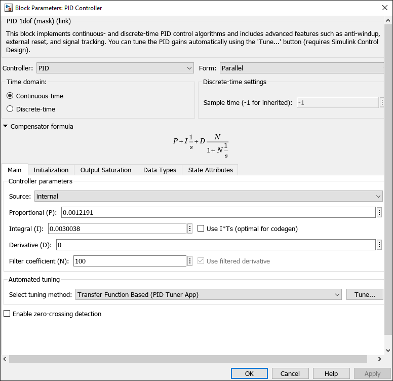
This example uses the Compensator Editor to tune Simulink blocks. When tuning a block in Simulink using Control System Designer, you can tune the block parameters directly or you can tune a zero-pole-gain representation of the block. For example, in the speed control example there is a PID controller with filtered derivative scdspeedctrl/PID Controller:

This block implements the traditional PID with filtered derivative as:

In this block P, I, D, and N are the parameters that are available for tuning. Another approach is to reformulate the block transfer function to use zero-pole-gain format:

This formulation of poles, zeros, and gains allows for direct graphical tuning on design plots such as Bode, root locus, and Nichols plots. Additionally, Control System Designer allows for both representations to be tuned using the Compensator Editor. The tuning of both representations is available for all supported blocks in Simulink Control Design™. For more information, see What Blocks Are Tunable? (Simulink Control Design)
Open Control System Designer
In this example, to tune the compensators in this feedback system, open a preconfigured Control System Designer session by double clicking the subsystem in the lower left-hand corner of the model.
Compensator Editor Dialog Box
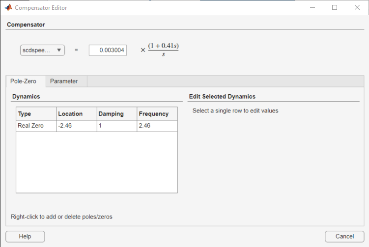
You can view the representations of the PID compensator using the Compensator Editor dialog box. To open the Compensator Editor, in the data browser, in the Controllers and Fixed Blocks section, double-click scdspeedctrl_PID_Controller. In the Compensator Editor dialog box, in the Compensator section, you can view and edit any of the compensators in your system.

On the Pole-Zero tab, you can add, delete, and edit compensator poles and zeros. Since the PID with filtered derivative is fixed in structure, the number of poles and zeros is limited to having up to two zeros, one pole, and an integrator at s = 0.
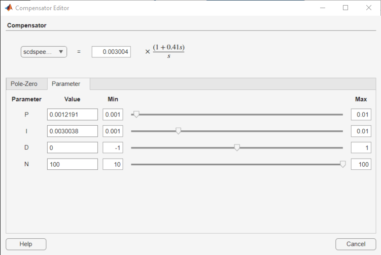
On the Parameter tab, you can independently tune the P, I, D, and N parameters.

Enter new parameters values in the Value column. To interactively tune the parameters, use the sliders. You can change the slider limits using the Min Value and Max Value columns.
When you change parameter values, any associated editor and analysis plots automatically update.
Complete Design
The design requirements in Single Loop Feedback/Prefilter Compensator Design (Simulink Control Design) can be met with the following controller parameters:
scdspeedctrl/PID Controller:
         P = 0.0012191
         I = 0.0030038
scdspeedctrl/Reference Filter:
         Numerator = 10
         Denominator = [1 10]
In the Compensator Editor dialog box, specify these parameters. Then, in Control System Designer, view the closed-loop responses.

Update Simulink Model
To write the compensator parameters back to the Simulink model, click Update Blocks. You can then test your design on the nonlinear model.
bdclose('scdspeedctrl')
See Also
Topics
- Edit Compensator Dynamics in Control System Designer
- Update Simulink Model and Validate Design (Simulink Control Design)