Main Content

pskdemod

Demodulate using M-ary PSK method

Description

example

z = pskdemod(y,M) demodulates the input M-PSK signals y. M specifies the modulation order.

example

z = pskdemod(y,M,phaseoffset) specifies the phase offset of the M-PSK constellation.

z = pskdemod(y,M,phaseoffset,symorder) specifies the symbol order of the M-PSK constellation.

z = pskdemod(y,M,Name=Value) specifies options using name-value arguments.

Examples

collapse all

Compare PSK and PAM modulation schemes to demonstrate that PSK is more sensitive to phase noise. PSK is more sensitive to phase noise because the PSK constellation is circular, while the PAM constellation is linear.

Specify the number of symbols and the modulation order parameters. Generate random data symbols.

len = 10000;                
M = 16;                     
msg = randi([0 M-1],len,1);

Create a phase noise System object™ and show the configured settings.

phasenoise = comm.PhaseNoise(Level=[-70 -80])
phasenoise = 
  comm.PhaseNoise with properties:

              Level: [-70 -80]
    FrequencyOffset: [2000 20000]
         SampleRate: 1000000
       RandomStream: 'Global stream'

Modulate msg using both PSK and PAM to compare the two methods.

txpsk = pskmod(msg,M);
txpam = pammod(msg,M);

Perturb the phase of the modulated signals.

rxpsk = phasenoise(txpsk);
rxpam = phasenoise(txpam);

Create scatter plots of the received signals.

scatterplot(rxpsk);
title('Noisy PSK Scatter Plot')
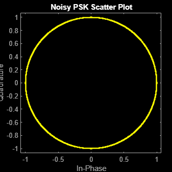
Figure Scatter Plot contains an axes object. The axes object with title Noisy PSK Scatter Plot, xlabel In-Phase, ylabel Quadrature contains a line object which displays its values using only markers. This object represents Channel 1.

scatterplot(rxpam);
title('Noisy PAM Scatter Plot')
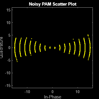
Figure Scatter Plot contains an axes object. The axes object with title Noisy PAM Scatter Plot, xlabel In-Phase, ylabel Quadrature contains a line object which displays its values using only markers. This object represents Channel 1.

Demodulate the received signals.

recovpsk = pskdemod(rxpsk,M);
recovpam = pamdemod(rxpam,M);

Compute the number of symbol errors for each modulation scheme. The PSK signal experiences a much greater number of symbol errors.

numerrs_psk = symerr(msg,recovpsk);
numerrs_pam = symerr(msg,recovpam);
[numerrs_psk numerrs_pam]
ans = 1×2

   286     1

Generate random symbols.

dataIn = randi([0 3],1000,1);

QPSK modulate the data.

txSig = pskmod(dataIn,4,pi/4);

Pass the signal through an AWGN channel.

rxSig = awgn(txSig,10);

Demodulate the received signal and compute the number of symbol errors.

dataOut = pskdemod(rxSig,4,pi/4);
numErrs = symerr(dataIn,dataOut)
numErrs = 3

Set the modulation order, then create a data sequence containing a complete set of constellation points.

M = 8;
data = (0:M-1);
phaseoffset = 0;

Visualize the plot constellations of 8-PSK symbol mapping for modulated and demodulated gray-coded and binary-coded data.

symgray = pskmod(data,M,phaseoffset,'gray',PlotConstellation=true, ...
          InputType='integer');

Figure contains an axes object. The axes object with title 8-PSK, Gray Mapping, xlabel In-phase Amplitude, ylabel Quadrature Amplitude contains 11 objects of type line, text. One or more of the lines displays its values using only markers

mapgray = pskdemod(symgray,M,phaseoffset,'gray',OutputType='integer');
symbin = pskmod(data,M,phaseoffset,'bin');
mapbin = pskdemod(symbin,M,phaseoffset,'bin',PlotConstellation=true, ...
         OutputType='bit');

Figure contains an axes object. The axes object with title 8-PSK, Binary Mapping, xlabel In-phase Amplitude, ylabel Quadrature Amplitude contains 11 objects of type line, text. One or more of the lines displays its values using only markers

Input Arguments

collapse all

M-PSK modulated input signal, specified as a scalar, vector, or matrix. If y is a matrix, the function processes the columns independently.

Data Types: double | single
Complex Number Support: Yes

Modulation order, specified as an integer value greater than 1.

Data Types: double

Phase offset of the PSK constellation in radians, specified as a scalar.

Data Types: double

Symbol order, specified as 'gray', 'bin' or a vector. This argument specifies how the function assigns binary vectors to corresponding integers.

  • 'gray' — Use a Gray-coded ordering.

  • 'bin' — Use a binary-coded ordering.

  • vector –– Use custom symbol ordering. The vector is of length M containing unique values in the range [0, M– 1]. The first element correlates to the constellation point corresponding to angle phaseoffset, with subsequent elements running counter-clockwise.

Name-Value Arguments

Specify optional pairs of arguments as Name1=Value1,...,NameN=ValueN, where Name is the argument name and Value is the corresponding value. Name-value arguments must appear after other arguments, but the order of the pairs does not matter.

Before R2021a, use commas to separate each name and value, and enclose Name in quotes.

Example: y = pskdemod(x,M,phaseoffset,symorder,OutputType='bit')

Type of output, specified as 'integer', 'bit', 'llr', or 'approxllr'.

Output data type, specified as one of the following:

OutputType ValueAcceptable OutputDataType Values
'integer''double', 'single', 'int8', 'int16', 'int32', 'uint8', 'uint16', or 'uint32'
'bit''double', 'single', 'int8', 'int16', 'int32', 'uint8', 'uint16', 'uint32', or 'logical'

The default value is the data type of input y.

Dependencies

To enable this argument, set the OutputType argument to either 'integer' or 'bit'. Otherwise, the output data type is same as the input data type y.

Noise variance, specified as one of these options:

  • Positive scalar — Use the same noise variance value on all input elements.

  • Vector of positive values — Use noise variance for all the elements of the input along the corresponding last dimension, specified by each element of the vector. The vector length must be equal to the number of elements in the last dimension of the input signal.

  • The demodulation function expects a complex input signal. In the case of BPSK, the modulator outputs a complex signal with a zero-valued imaginary part. If you instead input a real signal to the demodulator, you must represent the noise power of a complex signal in the real-valued input signal by setting the variance value to twice the variance of the real-valued input signal.

Tip

The exact LLR algorithm computes exponentials using finite precision arithmetic. For computations involving very large positive or negative magnitudes, the exact LLR algorithm yields:

  • Inf or -Inf if the noise variance is a very large value

  • NaN if the noise variance and signal power are both very small values

The approximate LLR algorithm does not compute exponentials. You can avoid Inf, -Inf, and NaN results by using the approximate LLR algorithm.

Dependencies

To enable this argument, set the OutputType argument to either 'llr' or 'approxllr'.

Data Types: double

Option to plot constellation, specified as logical 0 (false) or 1 (true). To plot the PSK constellation, set 'PlotConstellation' to true.

Output Arguments

collapse all

M-PSK demodulated output signal, returned as a scalar, vector or matrix with the same number of columns as the input signal y. The value and dimension of this output vary depending on the specified 'OutputType' value, as shown in this table.

'OutputType'pskdemod Output ValueDimensions of Output
'integer'Demodulated integer values in the range [0, M – 1]z has the same dimensions as the input y.
'bit'Demodulated bitsThe number of rows in z is log2(M) times the number of rows in y. The function maps each demodulated symbol to a group of log2(M) bits, where the first bit represents the most significant bit (MSB) and the last bit represents the least significant bit (LSB).
'llr'Log-likelihood ratio value for each bit calculated using the exact log-likelihood algorithm. For details, see Exact LLR Algorithm.
'approxllr'Approximate log-likelihood ratio value for each bit. The values are calculated using the approximate log-likelihood algorithm. For details, see Approximate LLR Algorithm.

References

[1] Proakis, John G. Digital Communications. 4th ed. New York: McGraw Hill, 2001.

Extended Capabilities

C/C++ Code Generation
Generate C and C++ code using MATLAB® Coder™.

Version History

Introduced before R2006a

expand all