FFT 기반 오버샘플링을 사용한 OFDM
이 예제에서는 OFDM+CP 신호를 수정하여 OFDM 변조기에서 오버샘플링된 파형을 효율적으로 출력합니다. 부반송파 간격 및 FFT 길이에 대한 샘플 레이트로 간단한 사례를 구성합니다.
k = 4;       % Number of bits per symbol
M = 2^k;     % Modulation order
nFFT = 128;  % Number of FFT bins
cplen = 8;   % CP length
txsymbols = randi([0 M-1],nFFT,1);
txgrid = qammod(txsymbols,M,UnitAveragePower=true);
txout = ifft(txgrid,nFFT);
txout = txout(:); % Vectorize matrix if processing multiple symbols
txcp = txout(nFFT-cplen+1:nFFT);
txout = [txcp; txout];

scs = 20e3;        % Subcarrier spacing in Hz
Fs = scs * nFFT/2; % Sampling rate (1.28e6 Hz)
Ts = 1 / Fs;       % Sample duration in seconds

Tend = Ts * (length(txout)-1);
subplot(211)
hold off
plot(0:Ts:Tend,real(txout),"*")
title("Real component of transmitter output")
subplot(212)
hold off
plot(0:Ts:Tend,imag(txout),"*")
title("Imaginary component of transmitter output")
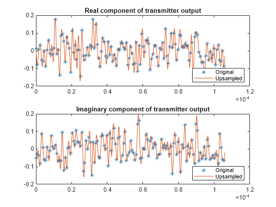
시간 영역에서 오버샘플링을 발생시키기 위해 FFT 길이를 nFFT보다 길게 정의합니다. 나중에 쉽게 비교할 수 있도록 txgrid 중간에 0을 삽입하여 원래 신호와 업샘플링된 신호의 Bin 중심값 간의 대응점을 유지합니다. 아래 제공된 컨트롤로 OFDM 변조기 출력과 복조기 입력에 사용되는 정수 오버샘플링 레이트를 조정할 수 있습니다.
upFactor =3; nFFTUp = upFactor * nFFT; fftgrid = [txgrid(1:nFFT/2); ... zeros((upFactor-1)*nFFT,1); ... txgrid((nFFT/2+1):nFFT)]; % Each column of fftgrid is one OFDM symbol txout = upFactor * ifft(fftgrid,nFFTUp); % Vectorize the matrix to process multiple OFDM symbols txout = txout(:); cplenUp = cplen * upFactor; txcp = txout(nFFTUp-cplenUp+1:nFFTUp); txout = [txcp; txout]; Ts = 1 / (upFactor*Fs); Tend = Ts * (length(txout)-1); subplot(211) hold on plot(0:Ts:Tend,real(txout)) legend ("Original","Upsampled","Location","southeast") subplot(212) hold on plot(0:Ts:Tend,imag(txout)) legend ("Original","Upsampled","Location","southeast")

잡음, 주파수 종속성, 지연을 추가하는 채널에 수신 신호를 통과시켜서 송신을 필터링합니다.
hchan = [0.4 1 0.4].';
rxin = awgn(txout,40);       % Add noise
rxin = conv(rxin,hchan);     % Add frequency dependency
channelDelay = dsp.Delay(1); % Could use fractional delay
rxin = channelDelay(rxin);   % Add delay
CP 길이보다 작은 랜덤 오프셋을 추가합니다. 오프셋을 0으로 설정하면 송신된 신호와 수신된 신호 간의 완벽한 동기화가 모델링됩니다. CP 길이보다 작은 타이밍 오프셋은 추가 선형 위상을 통한 이퀄라이제이션으로 보정될 수 있습니다. FFT 처리 전에 각기 다른 레이트의 신호를 직접 비교하기 위해 동기화된 신호를 업샘플링 인자로 정규화합니다.
offset = (randi(cplenUp) - 1); % random offset less than length of CP
% Remove CP and synchronize the received signal
rxsync = rxin(cplenUp+1+channelDelay.Length-offset:end);

rxgrid = fft(rxsync(1:nFFTUp),nFFTUp)/upFactor;
실제 시스템에서는 신호 복원 과정의 일부로 채널 추정이 필요합니다. OFDM과 CP를 결합하면 이퀄라이제이션이 각 주파수 Bin마다 하나의 복소수 스칼라로 단순화됩니다. 대기 시간이 CP 길이 이내에 있는 한, 채널 추정기에 의해 동기화가 이루어집니다. 아래 제공된 컨트롤로 수신기단에서의 이퀄라이제이션을 비활성화하여 실험해 볼 수 있습니다.
useEqualizer =true; if useEqualizer hfchan = fft(hchan,nFFTUp); % Linear phase term related to timing offset offsetf = exp(-1i * 2*pi*offset * (0:nFFTUp-1).'/nFFTUp); rxgrideq = rxgrid ./ (hfchan .* offsetf); else % Without equalization errors occur rxgrideq = rxgrid; end rxgridNoZeroPad = [rxgrideq(1:nFFT/2); ... rxgrideq((1+(upFactor-0.5)*nFFT):end)]; rxsymbols = qamdemod(rxgridNoZeroPad,M,UnitAveragePower=true); if max(txsymbols - rxsymbols) < 1e-8 disp("Oversampled receiver output matches transmitter input."); else disp("Received symbols do not match transmitted symbols.") end
Oversampled receiver output matches transmitter input.