Add and Connect AUTOSAR Classic Components and Compositions
After you create an AUTOSAR architecture model, develop the top-level AUTOSAR classic or adaptive software design. The composition editor provides a view of AUTOSAR software architecture based on the AUTOSAR Virtual Function Bus (VFB).
To begin, on the Simulink® Toolstrip Modeling tab, in the Platform section, confirm the architecture model is configured for Classic Platform. After that, starting at the top level of the architecture model, use the composition editor and the Modeling tab to add and connect AUTOSAR software compositions and classic components.
Alternatively, you can import a software composition from ARXML files. See Import AUTOSAR Composition from ARXML.
Add and Connect Classic Component Blocks
To add and connect AUTOSAR classic software components in an architecture model:
For each component required by the design, from the Modeling tab or the palette to the left of the canvas, add a Classic Component block. You can use the Property Inspector to set the component Kind —
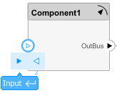
Application,ComplexDeviceDriver,EcuAbstraction,SensorActuator, orServiceProxy.Add component require ports and provide ports. To add each component port, click an edge of a Classic Component block. When port controls appear, select Input for a require port or Output for a provide port.
To connect the Classic Component blocks to other blocks, connect the block ports with signal lines.
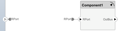
To connect the Classic Component blocks to architecture or composition model root ports, drag lines from the component ports to the containing model boundary.
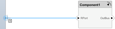
Releasing the connection creates a root port at the boundary.
You can automatically connect ports with the same name between components, see Auto-Connect Ports with Same Name (System Composer) for more information.
Configure additional AUTOSAR properties by using the Property Inspector.
For example, to author a simple design:
Using the Simulink Start Page, create an AUTOSAR architecture model. (For more information, see Create AUTOSAR Architecture Models.) The model canvas initially is empty.
Select the architecture platform, Classic or Adaptive.
From the Modeling tab, in the Platform section, select
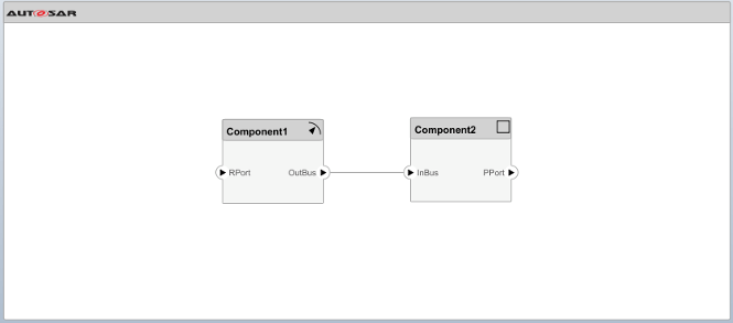
Classic
                            Platform
. Mixing classic and adaptive components in the same architecture model is not supported.From the Modeling tab or the palette, add two Classic Component blocks. Place them next to each other, left and right.
For each block, use the Property Inspector to set the component Kind —
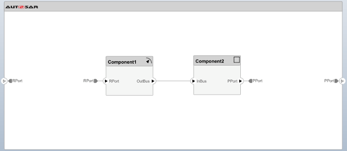
SensorActuatorfor the left block andApplicationfor the right block.Add a provide (output) port to the left component block and a require (input) port to the right component block. Connect the two ports.
Add a require (input) port to the left component block and a provide (output) port to the right component block.
Connect the new require and provide ports to architecture model root ports. Drag a line from each port to the model boundary.
The simple design is complete, but behavior is not yet defined for the AUTOSAR components. The next step is to add Simulink behavior to the AUTOSAR components by creating, importing, or linking models. See Define AUTOSAR Component Behavior by Creating or Linking Models. For a more detailed design example, see Author AUTOSAR Compositions and Components in Architecture Model.
If you have Requirements Toolbox™ software, you can link components in an AUTOSAR architecture model to requirements. See Link AUTOSAR Components to Requirements.
Add and Connect Composition Blocks to a Classic Model
To add and connect an AUTOSAR software composition nested in an architecture model:
From the Modeling tab or the palette to the left of the canvas, add a Software Composition block.
Add composition require ports and provide ports. To add each composition port, click an edge of the Software Composition block. When port controls appear, select Input for a require port or Output for a provide port.
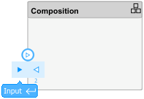
Alternatively, open the Software Composition block. To add each composition port, click the boundary of the composition diagram. When port controls appear, select Input for a require port or Output for a provide port.
To connect the Software Composition block to other blocks, connect the block ports with signal lines.
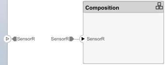
To connect the Software Composition block to architecture or composition model root ports, drag a line from the composition ports to the containing model boundary.

Releasing the connection creates a root port at the boundary.
Configure additional AUTOSAR properties by using the Property Inspector.
For example, to author a simple nested composition:
Using the Simulink Start Page, create an AUTOSAR architecture model. (For more information, see Create AUTOSAR Architecture Models.) The model canvas initially is empty.
From the Modeling tab or the palette, add a Software Composition block and a Classic Component block. Place them next to each other, left and right.
Add a provide (output) port to the left composition block and a require (input) port to the right component block. Connect the two ports.
Add a require (input) port to the left composition block and a provide (output) port to the right component block.
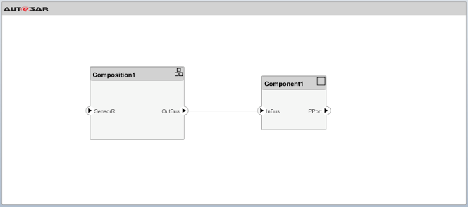
Connect the unconnected require and provide ports to architecture model root ports. Drag from each port to the model boundary.
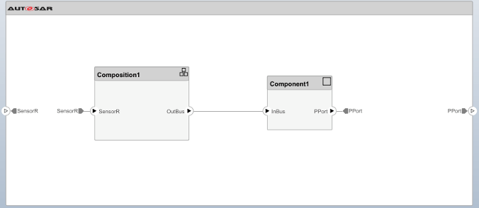
Typically, an AUTOSAR composition contains a set of AUTOSAR components and compositions with a shared purpose. To populate a composition, open the Software Composition block and begin adding more Classic Component and Software Composition blocks. For a more detailed design example, see Author AUTOSAR Compositions and Components in Architecture Model.
See Also
Classic Component | Software Composition
Topics
- Import AUTOSAR Composition from ARXML
- Add and Connect AUTOSAR Adaptive Components and Compositions
- Define AUTOSAR Component Behavior by Creating or Linking Models
- Create Profiles Stereotypes and Views for AUTOSAR Architecture Analysis
- Link AUTOSAR Components to Requirements
- Author AUTOSAR Compositions and Components in Architecture Model
- Configure AUTOSAR Architecture Model Programmatically